Saturday, May 9, 2015

Mill: Angular Contact Bearings

Please read the complete article:
http://benchtopmachineshop.blogspot.com/2017/04/mill-spindle-bearings.html


It turns out the new spindle I installed in my mill was ground at an angle. Fortunately, Grizzly sent me a new spindle without questions. Since you cannot remove the bearings in a X2 mini mill without destroying the bearings, I decided to take this opportunity to upgrade to angular contact bearings. I already had a pair of SKF ABEC-3 bearings on hand which I'd gotten for a good price.

The advantage of angular contact over deep groove bearings is the angular contact can take a much higher axial load, and are in fact designed for it. This also allows you to preload them much higher than deep groove bearings, and higher preload mean a stiffer spindle. Angular contact bearings are directional, meaning they can only take axial load in one direction. In fact, there is play between the bearing races until preload is applied.

Stock deep groove radial bearing on the left and angular contact bearing on right.

Before starting, I chucked the spindle in the lathe and sanded the top bearing seat with 400 sandpaper until the bearing was a light press fit. This will making setting the preload easier later on, and apply less static force on the bearing while doing so.

Instead of thermal fitting the bearings like last time, I decided to create a press for the bearing so I wouldn't have to remove the mill head. Since both the outer and inner races are a press fit, I needed to make adapters for the press which would push both inner and outer races equally. You never press a bearing through the rolling element or you'll destroy it! The adapters were made using two 3" diameter by 3" long pieces of aluminum rod, and a 2" diameter by 1" long steel rod. The press itself is a 5/8" long piece of threaded rod with a nut red Loctited onto one end.

The aluminum was faced on both sides, and then a 5mm long section was turned down to 60mm . The center was then drilled and bored out to 31mm. This allowed it to slip over the top of the spindle and press evenly on both inside and outside bearing race. It also allowed it to center over the top bore of the spindle head when pressing in the bottom bearing. The bottom adapter was again faced on both sides and the end of the ID turned down to 60mm. The center was drilled and bored out to 43mm, which is wide enough to not touch the inner bearing race. The steel rod was faced on both sides, and had the center drilled and bored out to 16.5mm, wide enough to clear the 5/8" threaded rod.

I then thermal fit the bottom bearing onto the spindle. Make sure the wide part of the outer race faces the top of the spindle, and the wider part of the inner race faces the bottom of the spindle. Remember that the angular contact bearings have play between the races until preloaded. With the aluminum bottom adapter in place I wanted roughly the midpoint of the play to put the spindle's nose flush with the adapter's surface. I kept taking facing cuts on the adapter until I reached that point. So with the play removed one direction the nose sat slightly under the adapter's surface's level and with the play removed the other direction it stood slightly proud.

To to press the bottom bearing and spindle into the mill head I put the 5/8" threaded rod through the center of the spindle, put the top adapter in place (the top bearing is installed later), put the bottom adapter in place over the spindle and bearing, placed the steel adapter over the bottom adapter, and ran the nut down on the threaded rod, holding everything together. The steel adapter supports the spindle's nose, which in turn supports the bearing's inner race. Since we adjusted the bottom adapter so the inner race would sit in the middle of its play, we can now press the bearing into place without applying any force to the inner race. I lightly oiled the bearing and the bore and tightened the 5/8" rod until the bearing pulled and seated into it's bore.

I then disassembled the top of the press, lightly oiled the top bearing and bore, and pressed it into place as well. On the top I needed additional clearance for the spindle, so I used a PVC pipe fitting; it worked just fine.

Bearing press assembled using old spindle and bearing.

Any high quality 7206 bearing is going to be open, unless you spend $300 for sealed ones. Initially I was worried that open bearings would quickly lose their lubrication, but in practice that hasn't been the case. To help retain the lubrication I took an old milk jug and using a compass cutter cut out seals which would sandwich underneath the plastic bearing covers. The ID of the seal was large enough that it would not rub in the inner race. In addition, I created a rubber shield between the plastic bearing cover and the spindle. I made it from EPDM sheet again using the compass cutter, and hot glued it into the plastic bearing cover's bore; the bore has a great little lip which makes it very easy. The seal is very close to, but does not touch the spindle. All in all, this setup keeps the lube in place nicely, and does a good job of dirt out. It also comes apart pretty easily in order to lube the bearings. For grease I used Lucas Red N Tacky which does a good job of staying put, is easy to get, and works well enough for the low spindle speeds I run (max 3,500 RPM).

Honestly, the system the X2 uses for preload adjustment isn't all that great or accurate. The absolute first thing I did was face both side of the adjustment nut. From the factory it's pretty far off. This will allow even pressure to be applied to the bearing. Next I took the set screw, cut the point off, and faced it. This would still provide enough holding power to keep the nut from turning, but wouldn't damage the spindle threads. To make adjusting the nut easier, I took a 32mm socket and ground it down until I had four teeth to interface with the nut; it's much easier than using a lock ring wrench.

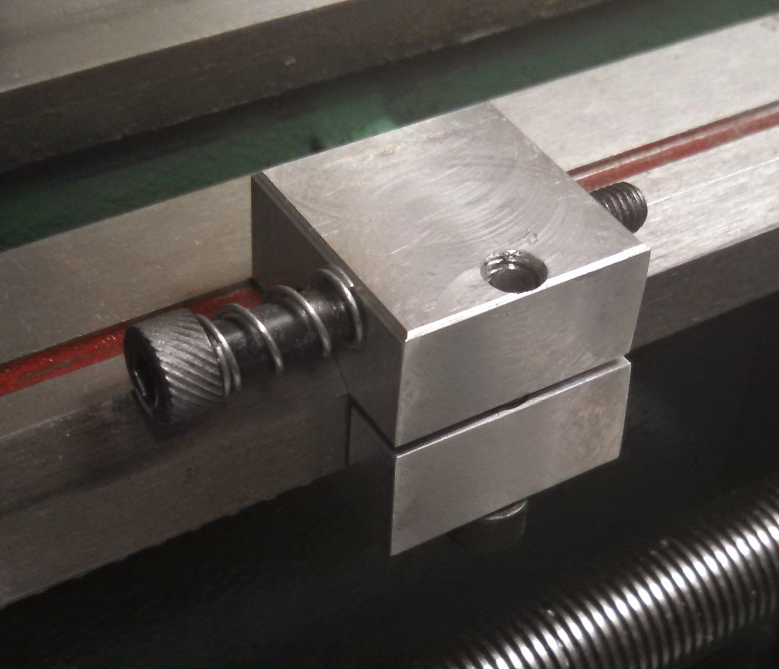
32mm socket ground down to fit the spindle nut. Regarding the finish, I did it with an angle grinder, so what do you expect?

Adjusting the preload was a little tricky, since I wanted to get between 100 and 125 pounds of preload. I measured how much torque was required to remove the play from the spindle, then I added 20 in/lbs of torque to that, and tightened down the but. It was roughly 55 in/lbs of torque. Using a DTI attached to the spindle, I checked for play in the spindle; you shouldn't see any play with properly preloaded bearings. Then I ran the mill at high speed for 30 minutes while monitoring the temperature of the mill head right next to the bearing. I used a IR thermometer which I pressed against the side of the mill head right at the bearing. I've checked the temperature at that location versus the temperature right at the bearing's outer race using a thermocouple and there is only a couple degrees difference. If the temperature stays under 60* C then you're fine on preload. On mine the temperature barely even reached 45* C. I then made sure to put a witness mark on the nut so I could tighten it to the exact same point every time.

UPDATE: Well, my sealing measures weren't enough and the lower bearing was contaminated. To make sure this doesn't happen again, I'm spending the money on SKF sealed 7206 angular contact bearings (7206 BE-2RZP). While Arc Euro Trade offers sealed angular contact bearings, they're P0/ABEC-1 precision which means a runout of 0.0005". The SKF bearings, on the other hand, offer a runout of between 0.00015" and 0.0003". On a mill low runout is especially important, as it effects tool chip load, especially on small diameter tools. http://benchtopmachineshop.blogspot.com/2017/01/mill-angular-contact-bearings-ii.html

Tuesday, April 28, 2015

Lathe: Chip Guard

I wanted a way to keep chips off the cross slide digital scale and the cross slide dovetails. Since I had several pieces of 2mm thick aluminum I cut two sections to fit and drilled 1.25mm holes which I epoxied neodymium magnets in. I now have two covers which stick to the top of the cross slide and do a pretty good job of keeping the chips away.


The two halves of the chip guard with the magnets epoxied in place.

The two halves of the chip guard in place on the cross slide.
The left side guard is longer to better protect the left dovetail.

UPDATE: I've since installed an extension on the back to better protect the cross slide dovetails and leadscrew.


Tuesday, April 21, 2015

Mill: Stacking Tolerances

I know my spindle has 0.0008" runout, so I marked the "high point" on the side of the spindle. In turn I've checked all my tooling and marked the "low point" on them. Then I always match up the marks when I mount the in the spindle, so the spindle's and tool's runout cancel each other out to some extent. For example, my ER25 collet chuck has 0.0005" runout (it's a cheap one from China), but when mounted in the spindle with the high and low points aligned I end up with with only 0.0003" runout total.

Monday, April 20, 2015

Mill: MT3 Spindle Release Improved


A while ago I modified an 8" C clamp to make releasing tooling from my MT3 spindle easier: http://benchtopmachineshop.blogspot.com/2013/06/mill-mt3-spindle-release.html. It worked OK, but the clamp would frequently slip off the drawbar or the clamp would slide to one side.

To fix it I removed the pad from the clamp, leaving just the ball. I then turned a spherical dimple in the top of the drawbar roughly the same size as the ball on the clamp. Now the ball mates to the drawbar and keeps it from sliding and directs all the force downward.

It's made the tool work much better and it's a breeze to release my MT3 tooling now.


Clamp with the pad removed from the screw, exposing the ball.

Dimple in the top of the drawbar which captures the clamp's ball.

Thursday, April 2, 2015

Mill: Bearing Replacement

Please read the complete article:
http://benchtopmachineshop.blogspot.com/2017/04/mill-spindle-bearings.html


After boogering up my spindle I was forced to replace it. While I was at it I decided to replace the cheap bearings with high quality Japanese bearings. The procedures you see for mini mill bearing replacements will work, but the methods used put unneeded stress on the bearings and require some specific tools. I decided to do it an easier and better way.

The mill uses deep groove radial bearings. They're not ideal for a mill spindle, but they'll work adequately. Since I have a MT3 spindle I use two 6206 bearings, and you can get them either sealed or shielded. Shielded actually have a tiny gap between the shield and the inner race, so they don't protect as well, but they also produce less heat and have a higher top speed. Sealed protect the bearing better, but they'll produce noticeably more heat and, once they're installed and preloaded, their top speed will be about the same as the top speed of a belt driven mini mill.

Most Japanese bearings, even if they're listed as ABEC-1 will actually be ABEC-3. Really, either is good enough for the tolerances of the mini mill. A lot of replacement 6206 bearings you see are C3 tolerance. The C3 indicates they have greater clearance inside the bearings. On the mini mill they should be ok to use since the bearings are preloaded. You can also use CN (normal internal clearance) or C2 (reduced internal clearance). I ended up with SKF sealed C2 bearings since that's what was readily available to me.

Getting the bearings out wasn't hard. As I hammered the spindle out using a rubber mallet it pushed the bottom bearing out. The top bearing was removed using a piece of pipe and a mallet. The bearing bores were thoroughly cleaned and lightly oiled.

First I needed to install the new bearings in the mill head. To do so I removed the mill head (you'll need to remove the motor to do so) and put it in the oven at 220* F for 1.5 hours. The previous evening I put the bearings in the freezer. After using my IR thermometer to make sure the mill head was up to temperature, I took it out of the oven and pushed the two bearings into place. You have to be quickly because the heat iron will quickly heat up and expand the bearings.

If you can't do it, or couldn't get the bearing all the way in before getting stuck, you'll need to press it the rest of the way in. The key is you can only press the bearing on the outer race. The way I do this is take the old bearing, remove the shield from one side, and grind the inner race down. Now you can use the old bearing to push the new bearing in without applying pressure to the inner race. I then use a 1/2" threaded rod, a couple nuts, and several thick washers to push it into place.

Installing the spindle is a similar procedure. I put the spindle in the freezer overnight and the mill head, with the bearings in it, went back in the oven at 200* F. I put a very light mineral oil on the spindle to help lube it during assembly. Once the mill head was up to temperature I quickly removed it and seated the spindle in place. I had to tap it once or twice with a rubber mallet when it jammed during insertion. However, I never had to hit it very hard so it didn't damage the bearings.

Once everything was together I reassemble the mill, head, and motor. I then tightened the reverse thread nut on top of the spindle down tight to remove the play from the bearings, backed it off slightly, and tightened down the set screw.

Once back together I ran in the bearings using the SKF recommended procedure, basically running the mill in increments of 500 rpm until the bearing housing temperature stabilized.

UPDATE: Well, the new spindle's bore was ground at a slight angle, so I replaced the spindle for a second time. This time using angular contact bearings: http://benchtopmachineshop.blogspot.com/2015/05/mill-angular-contact-bearings.html.

Monday, March 9, 2015

Lathe: QCTP Tool Holders

The inside bottom corner of the 0XA tool holder (and I suspect pretty much any other QCTP tool holder) has a slight radius. This helps prevent a stress riser from forming in the corner and a crack forming. However, this doesn't allow tool bits to rest against both the bottom and side of the tool holder.

Since I'm not going to mill a sharp corner in the tool holder for the reason above, this left remove the corner from the tool bit instead. Since I mostly use indexed tools I just clamped the tool in my angle vise at 45* and milled just a little amount off the edge. This gives enough clearance for the radius in the tool holder and allows the tool to sit flush against the bottom and side.

For my non indexed tool bits I just run the edge along the grinding wheel just enough to knock the corner off.

Edge milled off tool bit holder and sanded smooth.

Lathe: Setting Tool Bit Height

I had a hard time quickly and accurately setting my tool bit height, and finally found a solution using an old inch -only dial caliper I didn't use anymore. After chucking a piece of aluminum in the lathe I took a couple cuts. I then measured from both the top and bottom of the turned portion to the top of the cross slide. Averaging those measurements gave me the distance from the top of the cross slide to the center of the work. I then set my old dial calipers on end on top of the top slide and adjusted the outside movable jaw until it was exactly that distance from the cross slide.

Now to adjust tool height I set the caliper on end on the cross slide and adjust the tool bit until it just clears the outside movable jaw on the caliper.

Setting tool bit height. I want the bit to just graze the caliper as it slides under the jaw.

Lathe: Compound Slide Delete

There's more potential play in the compound slide than I originally expected. It because very apparent when my parting blade jammed in the work and I saw the entire compound rotate on the gib. Since I only use the compound for threading and cutting tapers, it made sense to replace it with a solid chunk of metal.

The clearance between the top slide and chuck center is 55mm, so I carried that clearance over to the steel block. I realized setting it up for the largest diameter work it could handle would compromise doing small diameter work (which is the majority of what I do), so I made the block reversible, hence the two set of screw holes. The back of the block is relieved at 22* for work clearance when in the large diameter position.

In large diameter position.
In small diameter position.

To better support the QCTP I took a 3/16" hot rolled steel plate, milled top and bottom flat, and cut a shallow channel in the bottom the same width as the top of the steel block, keeping it positioned side to side.

It uses the existing compound mount, which also makes re-installing the stock compound slide very easy. The new setup works very well and has noticeably increased the rigidity of the lathe.


With 0XA QCTP mounted.


Friday, March 6, 2015

Cold Rolled Steel

I learned a lesson the hard way on using cold rolled steel. There are tensile stresses in the skin of the steel extending 0.5mm to 1.5mm deep. So if you do anything other than just drill holes, the steel will warp in some interesting ways. If you are going to use cold rolled, then you either need to stress relieve it (which is hard if you don't have a forge or furnace) or you need to mill at least 1.5mm off every face.

Instead of using cold rolled, from now on I'm going to use hot rolled steel which simply doesn't suffer from this.

Tuesday, March 3, 2015

Mill: Y-Axis Gib

Please read the complete article:
http://benchtopmachineshop.blogspot.com/2017/04/mill-gibs.html


Substitute the mini mill Z-axis gib for the Y-axis gib. You'll need to cut it to length, but the Z-axis gib sits much better and takes up nearly all the space available.

Wednesday, February 25, 2015

Mill: Kurt-Style Vise

Please read the complete article:
http://benchtopmachineshop.blogspot.com/2017/04/mill-vises.html


After using my screwless vise for over half a year I've become kind of fed up using it as my everyday vise. The hassle of adjusting it to hold different parts and trying to re-position the jaw constantly interrupted and slowed down the work. The modifications I made had improved it, but not enough.

I ended up getting a 3" Kurt-style milling vise. The Kurt-style vise forces the moving jaw downward as it's tightened, which keeps the part from lifting. While it's not quite as precise as the screwless vise, it is a lot nicer and faster to use. If I need the extra precision I'll just mount the screwless next to it.

The first thing I did was take it apart and clean it up. It turn out the casting for the jaw where it meets was the nut was deformed with extra material in the jaw. Using my Dremel I cut away the extra. Also with the Dremel I smoothed out the location where the hemisphere rides in the jaw. After this I lubed it up and reassembled it.

At the end of the day if I could only have one vise I'd go with the screwless vise just for its precision and multiple ways of mounting it.

Lathe: Carriage Stop

Decided to make a carriage stop for the lathe. Even though I have the DRO, it's nice to just move the carriage until it stops instead of to a number. It was just made from aluminum, and the screw to tighten it was moved to the bottom so it wouldn't interfere with the ways protectors I have installed. Currently you need an allen key to tighten/loosen it, and I probably won't change that since I don't see myself using it all that much.


Lathe: Compound Lock and Gib

The compound slide gib is not nearly robust enough for the forces you can see, especially when parting and threading. I've seen the whole compound rotate over on the gib when the parting blade jammed. To remedy this I added to both add a gib lock and to add an extra gib set screw.

I removed the top of the compound and clamping it in the mill and drilled and tapped two extra holes located exactly between the existing set screws. After modifying the gibs (http://benchtopmachineshop.blogspot.com/2015/01/lathe-gibs.html) I put a dog nose on a M4 SHCS and installed it in the middle set screw hole. Now the compound has more support overall and I can easily lock it in place.

Extra gib set screws with the gib lock right in the middle.

Monday, February 9, 2015

Mill: Screwless Precision Vise

Please read the complete article:
http://benchtopmachineshop.blogspot.com/2017/04/mill-vises.html


One of the biggest annoyances using the precision screwless vise was loosening the jaw and accidentally unscrewing it from the T bracket which holds the cross bar that hooks into the base. After having it happen it again in the middle of a project I took the screw which connects the jaw to the T and turned it smooth starting 5 threads from the end.

Middle section of screw turned smooth.

I then ground a flat on the T right where it threads onto the screw. I then assembled the vise, threaded the screw into the T, and peened the flat to capture the screw. Now, no more accidentally unscrewing it.

Wednesday, February 4, 2015

Bandsaw Vise

I wanted to add a bandsaw to my workshop, but because of limited space I needed something small. The Grizzly G8692 portable bandsaw and stand were the right size and definitely the right price.

The big problem was the included vise. It was too flimsy and stood way too far away from the blade. If you're never cutting a piece less than 12" long it might work, but it's utterly useless cutting anything short.

The first thing I did was move the vise toward the saw by 1.5". That's as close as I could get it without the saw hitting the vise. At this distance the saw cuts slightly into the vise base, but that's fine. The vise's quick release lever needed to be slightly shortened so it wouldn't interfere with the saw. The bolt also interfered with the saw so I switched it out for a socket head cap screw on which I turned the head down to a smaller diameter.

Then I cut sections of 2" wide 1/8" steel plate to extend the vise jaws all the way to the edge of the saw blade. In addition, the fixed saw got an extra 1/8" plate bolted to its back to help stiffen it more. The plates and jaws were welded together at their edges. A brace was also added between the fixed jaw and the base.

1/8" steel reinforcing plates welded into place.


Brace welded in place.

Since the moving jaw on the bandsaw vise is on a pivot, if what you're clamping doesn't extend beyond the pivot, the whole jaw will rotate and won't clamp. To fix this I drilled a 1/2" hole in the fixed jaw on the end of the vise opposite the saw, and welded a 5/16" nut to the outside of it. I then took a piece of 5/16 threaded rod, red Loctited two nuts onto the end, turned the other end flat and chamfered it, and then threaded it through nut. Now I can quickly thread the rod through to space the moving jaw correctly.

Threaded rod in place, screwed all the way out.

Threaded rod adjusted in to space the moving jaw.


It's still not perfect, but it's very usable now.


Tuesday, January 27, 2015

Lathe: Gibs

I finally took the time to modify my lathe's cross slide and compound gibs the same way I did my mills: http://benchtopmachineshop.blogspot.com/2013/06/mill-gibs.html

The big difference was the lathe's gibs use a 60 degree angle versus the mill's 55 degree angle.

In addition, I also added two extra set screws on both the compound and cross slide in order to give it some extra rigidity. In the picture of the cross slide's set screws you can see I used three different type. The two stock ones were used due to clearance issues, the hex head was used because it's always behind the DRO read head and the hex head allows for adjustment, and the two socket head cap screws were used due to ease of adjustment. It looks a little sloppy, but aids in usability.

After cutting the pockets I reassembled everything with a generous amount of Mobil Vactra way oil on the gibs and ways. While I expected an improvement in the feel, I didn't expect the huge improvement I actually got. Even though they're snug and there isn't any play, both compound and cross slide move very smoothly and easily now. The difference is amazing.

The menagerie of set screws.

Friday, January 23, 2015

Lathe: Leadscrew Handwheel

One of my biggest problems with the lathe is the carriage hand wheel isn't very precise for Z axis movement; it's hard to always stop it exactly. I don't like using the compound for fine Z axis movement since while carriage has a DRO on it, the compound does not. Also, I want to remove the compound eventually and replace it with a solid block of steel; the compound reduce rigidity of the system and I only use it for threading operations.

I know if I could attach a hand wheel to the leadscrew then I could put the leadscrew in neutral, lock the half nut, and slowly turn the leadscrew to move the carriage.

I decided to extend the leadscrew shaft past the pillow block to make a mounting point for the hand wheel. I removed the leadscrew, chucked it in the lathe, and drilled a hole in the end. It's already been center drilled which made things easier. I then took 1/2" steel rod (stolen out of an old ink jet printer) and turned down the end of it to the same size as the new hole in the leadscrew, making sure to leave a precise shoulder. After mating the rod and leadscrew together I welded around the seam, and then turned the weld bead down in the lathe.


Leadscrew extension sitting beyond the pillow block.
I bought a hand wheel from Amazon: http://www.amazon.com/dp/B00EDKIK9G. Since it had a 10mm bore I turned the lead screw extension down to 10mm. I took the hand wheel and drill and tapped three holes in it to accept set screws. After positioning the wheel where I wanted it on the shaft I installed the first set screw fairly hard in order to mark the shaft well. I then remove it and the hand wheel, turned an extended nose on the set screw, and drilled a shallow hole at the marked spot on the shaft. I then reassembled everything and made sure the set screw seated into the hole. I then installed the other two set screws.

It ended up working really well and I now have easy fine Z axis adjustment.

I left the shaft slightly longer than necessary to allow for future adjustments.
The new hand wheel set screws are visible.