Even a mini mill or mini lathe can seriously hurt or even kill you, but some machine tool safety rules can be a little counter intuitive:
- Never wear gloves. Even though you'll end up with more cuts and splinters, the work or tooling can easy grab a glove and pull your hand and arm into the machine. On a large machine once it's pulled your arm in, it can easily pull the rest of you in as well.
- Never wear long sleeves. Similar reasons as above, as a sleeve can easily get grabbed and pulled in.
Monday, September 16, 2013
Friday, June 21, 2013
Mill: Packaging My Android DRO
Please read the complete article:
http://benchtopmachineshop.blogspot.com/2017/04/mill-touchdro.html
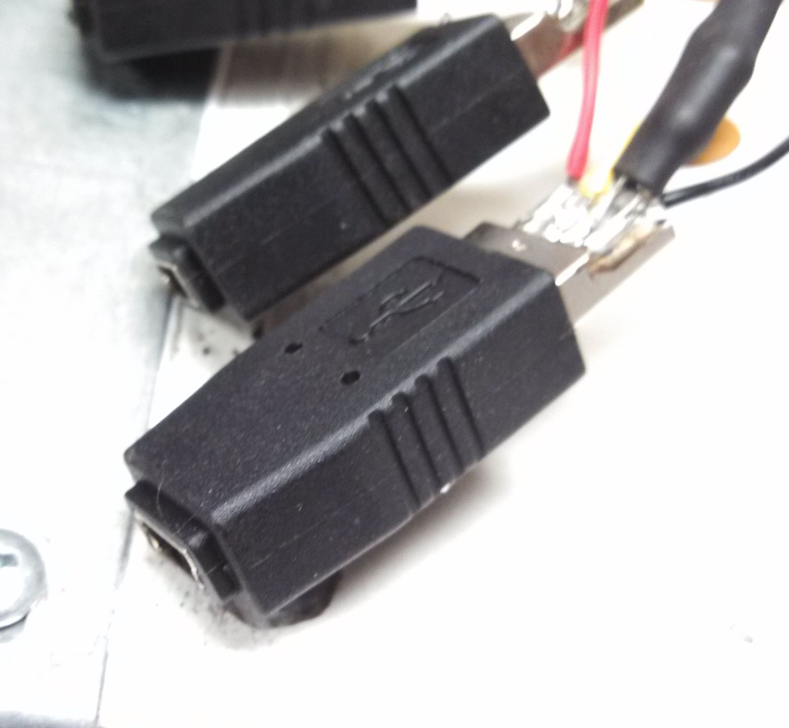
I finished packaging the Android DRO. It went into a Radio Shack project box which I machined slots in for the USB adaptors to stick out through. I wedged them in there and glued them in place with two part epoxy. I also cut a hole for the USB cable which will provide power. To mount the Arduino I secured a thin piece of wood in the bottom of the project box, which the Arduino is then screwed to.

I then used Sugru to make the USB connectors look pretty, enclose the USB power cable, and provide it with strain relief.

Thanks to my mom for helping with the Sugru molding. If you haven't used it before, Sugru is a really useful thing to have in your tool box. It comes in little packets and it's silicone rubber which sticks to most things and is moldable for 30 minutes after opening, and cures in 24-48 hours.

http://benchtopmachineshop.blogspot.com/2017/04/mill-touchdro.html
I finished packaging the Android DRO. It went into a Radio Shack project box which I machined slots in for the USB adaptors to stick out through. I wedged them in there and glued them in place with two part epoxy. I also cut a hole for the USB cable which will provide power. To mount the Arduino I secured a thin piece of wood in the bottom of the project box, which the Arduino is then screwed to.

I then used Sugru to make the USB connectors look pretty, enclose the USB power cable, and provide it with strain relief.

Thanks to my mom for helping with the Sugru molding. If you haven't used it before, Sugru is a really useful thing to have in your tool box. It comes in little packets and it's silicone rubber which sticks to most things and is moldable for 30 minutes after opening, and cures in 24-48 hours.

After that the USB cable was hot glued into the USB jack on the Arduino, the unit was tested again, and then the top was screwed in place. Done! I don't think I'll mount it on the mill itself since it doesn't really need to be. Oooooooor I may mount it.
 | |||||||
| All packed up and ready to go. |
Monday, June 17, 2013
Mill: Android DRO
Please read the complete article:
http://benchtopmachineshop.blogspot.com/2017/04/mill-touchdro.html
First off, all credit to Yuriy Krushelnytskiy of http://www.yuriystoys.com/.
While poking around the internet for information on the X2 mill, I stumbled on Yuriy's blog. What really intrigued me was his DRO application for the Android: http://www.yuriystoys.com/search/label/DIY%20DRO%20Project
He was using iGaging digital scales, which most X2 owners end up using when installing DROs, connected to an Arduino, which interfaced with an Android via Bluetooth. The DRO app he wrote took the input from the digital scales and displayed it in a nice interface. Just that alone had my attention since the included iGaging remote LCD displays were a little hard to see. However, since all the work is being done in software, it'll be easy to add new features to the DRO in the future. Additionally, since it's open source, you can always add a must have feature yourself. Now that Androids have gotten cheap enough and powerful enough, it makes a lot of sense to do in software what traditional DROs did in hardware. Doing it in software is just much cheaper and much more flexible.
The app is already available in Google Play Store.
Since I had my old HTC Incredible 2 Android phone sitting around I decided to use that instead of a tablet. However, Android DRO needs at least Android v.3 to run, so I needed to root the phone and load a newer Android version. Additionally, once you have Android DRO loaded, if you're using a 4" screen or smaller you'll lose the buttons on the right. To fix this the app needs to be recompiled using Eclipse, which is included in the free Android SDK. You'll need to download the source code and import the project into Eclipse, fix the broken link in the build path, add "Android 4.2.2" and "Android Private Libraries" to your build path, and then drill down to res>values>dimens.xml and change font_lcd from 100dp to 85dp. Then go to "Android Tools" and save it as a signed APK. Go through the wizard, and then use ADB to install the APK file.
I also wanted to reduce the digits displayed. Currently the app shows 0.0001" and 0.001mm, which is greater than the resolution of my iGaging scales, therefore it just clutters the screen with unusable information. Plus, good luck getting 0.0001" precision out of a mini mill. To change it I went to res>values>strings.xml and changed inch_mask to "88.888", inch_format to "00.000", mm_mask to "888.88", and mm_format to "000.00". Since I removed a digit, I was able to cheat the font bigger again, and set font_lcd to 95dp. I again saved it as a signed APK and installed it on the phone.
For the Arduino I bought the Leonardo model which comes without headers, since I like soldered connections. HOWEVER, I learned the hard way the app does NOT like the Leonardo. The app would connect, and then immediately lose connection. Once I switched from the Leonardo to the Uno R3 everything started working beautifully. The Uno R3 comes with headers, so I needed to cut them off and de-solder the pins so I could solder the leads in place.
The iGaging scales connect to the remote readouts via mini B USB connectors. I couldn't for the life of me find a cable with a female mini B USB connection on it, so I settled for adaptors instead. I opened up the end opposite from the mini USB and soldered my leads directly to the pins. Once everything was soldered and tested I covered all the connections with epoxy.


I bought a small project box from Radio Shack, and aside from the very annoying issue with the Leonardo, the hardest part was installing everything inside the box.
http://benchtopmachineshop.blogspot.com/2017/04/mill-touchdro.html
First off, all credit to Yuriy Krushelnytskiy of http://www.yuriystoys.com/.
While poking around the internet for information on the X2 mill, I stumbled on Yuriy's blog. What really intrigued me was his DRO application for the Android: http://www.yuriystoys.com/search/label/DIY%20DRO%20Project
He was using iGaging digital scales, which most X2 owners end up using when installing DROs, connected to an Arduino, which interfaced with an Android via Bluetooth. The DRO app he wrote took the input from the digital scales and displayed it in a nice interface. Just that alone had my attention since the included iGaging remote LCD displays were a little hard to see. However, since all the work is being done in software, it'll be easy to add new features to the DRO in the future. Additionally, since it's open source, you can always add a must have feature yourself. Now that Androids have gotten cheap enough and powerful enough, it makes a lot of sense to do in software what traditional DROs did in hardware. Doing it in software is just much cheaper and much more flexible.
The app is already available in Google Play Store.
Since I had my old HTC Incredible 2 Android phone sitting around I decided to use that instead of a tablet. However, Android DRO needs at least Android v.3 to run, so I needed to root the phone and load a newer Android version. Additionally, once you have Android DRO loaded, if you're using a 4" screen or smaller you'll lose the buttons on the right. To fix this the app needs to be recompiled using Eclipse, which is included in the free Android SDK. You'll need to download the source code and import the project into Eclipse, fix the broken link in the build path, add "Android 4.2.2" and "Android Private Libraries" to your build path, and then drill down to res>values>dimens.xml and change font_lcd from 100dp to 85dp. Then go to "Android Tools" and save it as a signed APK. Go through the wizard, and then use ADB to install the APK file.
I also wanted to reduce the digits displayed. Currently the app shows 0.0001" and 0.001mm, which is greater than the resolution of my iGaging scales, therefore it just clutters the screen with unusable information. Plus, good luck getting 0.0001" precision out of a mini mill. To change it I went to res>values>strings.xml and changed inch_mask to "88.888", inch_format to "00.000", mm_mask to "888.88", and mm_format to "000.00". Since I removed a digit, I was able to cheat the font bigger again, and set font_lcd to 95dp. I again saved it as a signed APK and installed it on the phone.
For the Arduino I bought the Leonardo model which comes without headers, since I like soldered connections. HOWEVER, I learned the hard way the app does NOT like the Leonardo. The app would connect, and then immediately lose connection. Once I switched from the Leonardo to the Uno R3 everything started working beautifully. The Uno R3 comes with headers, so I needed to cut them off and de-solder the pins so I could solder the leads in place.
 |
| Uno R3 with the headers and pins removed. |

Demo moving the X and Y axis
Thursday, June 13, 2013
Mill: Bench Top Precision Belt Kit
I decided to preemptively upgrade my mill to belt drive. This way I never have to deal with broken gears, and the mill runs quieter as well. Since I frequently work later at night that's a nice benefit. After researching kits for a while, I found the one made by Bench Top Precision:
http://www.benchtopprecision.com/x2_belt_drive_kit.html
It looked identical to the Little Machine Shop kit, but was significantly cheaper (prices have gone up since I bought it) so I went with it. The seller was great to work with, and the money I saved allowed me to buy additional tooling. After receiving it I see there are a couple notable difference between it and the one from LMS:
Installation was easy, and took less than 30 minutes. Please note you want to install the motor standoffs on the base plate before installing the base plate on the mill. One annoying note is the kit was a mix of metric and Imperial allen bolts, especially since the mill is all metric.

http://www.benchtopprecision.com/x2_belt_drive_kit.html
It looked identical to the Little Machine Shop kit, but was significantly cheaper (prices have gone up since I bought it) so I went with it. The seller was great to work with, and the money I saved allowed me to buy additional tooling. After receiving it I see there are a couple notable difference between it and the one from LMS:
- The LMS kit pulleys use the the stock shaft keys while the BTP kit uses dual set screws, one of which seats in the key way of the shaft.
- The LMS kit has you re-tighten the spindle nut's set screw. On the BTP kit it's inaccessible so instead you use Loctite on the threads.
- The LMS motor pulley is seated down all the way on the motor's shaft, while on the BTP kit the motor pulley is visually aligned with the spindle pulley and then tightened.
Installation was easy, and took less than 30 minutes. Please note you want to install the motor standoffs on the base plate before installing the base plate on the mill. One annoying note is the kit was a mix of metric and Imperial allen bolts, especially since the mill is all metric.

Monday, June 10, 2013
Mill: Labels
I put labels on the mill's hand wheels indicating which direction the table moves. This helps prevent me from accidentally turning the wheel in the wrong direction at the end of a cut.


Lathe: Crank Retaining Bolts
The stock retaining bolts for the cross slide and compound cranks are socket head cap screws. I was constantly hitting my knuckles on them and was annoyed by them whenever I used my lathe.

They sit the lathe's cranks perfectly. The only issue is you need to put a pair of washers between the crank and dial to space it correctly. The new bolts almost sit flush with the cranks and I have yet to hit my knuckles on them again. The bolts should be available in most bike shops.

I realized that some Avid Single Digit v-brakes for bicycles come with retaining bolts with the socket head sunk into the body of the screw itself:

Sunday, June 9, 2013
Lathe: Cross Slide DRO
Please read the complete article:
http://benchtopmachineshop.blogspot.com/2017/04/lathe-touchdro_12.html
I've wanted a DRO on my lathe's cross slide for a while to deal with the back lash and confusing dial markings. I bought s digital caliper to adapt to the role, like I've seen several people do before. However, I want to make sure I still had rotation of the compound slide. I ended up mounting next to the side of the cross slide, with the caliper's readout mounted stationary to the carriage via a bolt through the base of the display.
I wish I could give directions on how to do it, but individual calipers are built differently, so there's a very good chance what worked for me won't work for you. You just need to buy a caliper and fool with it until it works.
Even though this is an annoying modification, I'd highly recommend it just for the added usability.

Wednesday, June 5, 2013
Mill: Gibs
Please read the complete article:
http://benchtopmachineshop.blogspot.com/2017/04/mill-gibs.html
I think the gibs which come with the mill are fine, except the divots for the set screws are woefully inadequate. Because the set screws aren't pushing against a flat, they tend to rotate the gib, which compromises rigidity and creates uneven wear.


I figured if they had a flat nose to push against a flat surface, they'd work a lot better and wouldn't deform. So it was disassembled and thrown in the lathe where its end was extended and faced flat. Since its end turns on the gib I greased it just before assembly.

http://benchtopmachineshop.blogspot.com/2017/04/mill-gibs.html
I think the gibs which come with the mill are fine, except the divots for the set screws are woefully inadequate. Because the set screws aren't pushing against a flat, they tend to rotate the gib, which compromises rigidity and creates uneven wear.

To fix this I decided to machine proper flats into the gibs for the set screws to sit on. First I removed all the set screws for the gib, then installed and positioned the gib. I sharpened the end of two M4 set screws in my lathe and first installed one and tightened it down, and then tightened the other one in each hole in turn. This left exact center marks for all the set screws. From measurements it looks like the gib angle is 55*, so I used my Wixey angle gauge to set my angle vise. Since the gib wanted to rotate when the vise was tightened, I placed a section of 1/2" steel rod in the corner formed by the gib and vise jaw, and then used my table clamp set to push down on the rod, effectively locking the gib in place. I then machined the flats using a 3/16" end mill with a plunge cut. For the lock's flat I used a 1/4" end mill. By the way, that gouge you see is what happens when your vise decides to let go of the work.

The set screws were also upgraded from the stock dog point to cup point. The last couple millimeters of the set screws were turned down so they just fit in the gib pocket. This helped position the gib horizontally and keep it from sliding on the set screws.
I also took the opportunity to lap the gib slightly, but it turned out it was pretty flat to begin with. Once everything was reassembled, the gib has much more contact with the dovetail, and I can tighten the set screws tighter without making it hard to move. It was well worth it in my opinion.
I didn't like how the gib locks looked either. They have a rounded nose which pretty quickly becomes deformed through use.

I figured if they had a flat nose to push against a flat surface, they'd work a lot better and wouldn't deform. So it was disassembled and thrown in the lathe where its end was extended and faced flat. Since its end turns on the gib I greased it just before assembly.

Tuesday, June 4, 2013
Mill: MT3 Spindle Release
The X2 comes with either a R-8 or MT3 spindle taper, with my mill having the MT3. Aside from there being more tooling available for R-8 it's biggest advantage that it's self releasing. To release an MT3 which has been over tightened will require much beating with a hammer on the drawbar. Even release a lightly tightened MT3 means at least one hit with a hammer. Personally, I don't like hitting my mill with a hammer.
However, even though I could change the spindle to R-8 for $60, I like that MT3 offers me more Z axis clearance. I also don't particularly want to spend $60. To allow me to eject the tool without having to use a hammer, I bought an 8" C clamp for $14 and cut the end off to give it enough clearance when there's a tool in the spindle. To eject the tool I simply loosen the drawbar, put the clamp in place with the base on the bottom of the spindle and the top of it on the drawbar, and then tighten it until it pushes the tool out of the spindle.


UPDATE: I modified the bottom of the clamp to better support the bottom of the spindle.

Sunday, June 2, 2013
Mill: Gas Spring Installation
After going back on forth on whether the gas spring was worth it or not, I decided to go ahead and do it. The added Z axis travel would be nice, and getting rid of the inconsistent torsion spring would make mounting the Z axis DRO much easier.
One thing I didn't like about the install was it wanted me to drill a half inch hole in the back of the column. I'm not a huge fan of putting holes in my column. Instead, I grabbed a piece of 1.5" UHMW tube left over from another project, cut it down to 5 inches long, and then squeezed it into an oval cross section using my bench vise and heat gun. I then drilled a 8mm hole through it 4.5" from the end. One end of the gas spring is bolted through using the hole, and it's then lowered down onto the column. The UHMW tube then site on the mill's base inside the column and spaces the gas spring correctly. This way there's one less hole in my column.
On a related note, UHMW is a horrible plastic to machine. Use something else unless it's absolutely necessary.


Ultimately, I think for the money this upgrade is worth it. It's not a huge difference, but it makes the mill nicer to use and definitely made mounting the Z axis DRO much easier. It also doesn't stick up above the mill as high as I thought it would. From the picture you can see it only sits a couple inches above the motor.
Lathe: Favorite Tool Bit
I love this tool bit set up:

It's two carbide tipped tool bits I bought from Amazon (only $3 each) and mounted back to back in a tool holder. This allows me to switch from turning to facing extremely quickly and easily. The turning bit will get a lot more use, so when it starts to dull I'll just switch the two.

It's two carbide tipped tool bits I bought from Amazon (only $3 each) and mounted back to back in a tool holder. This allows me to switch from turning to facing extremely quickly and easily. The turning bit will get a lot more use, so when it starts to dull I'll just switch the two.
Saturday, June 1, 2013
Mill: Z-Axis DRO
Please read the complete article:
http://benchtopmachineshop.blogspot.com/2017/04/mill-touchdro.html
Once I installed the gas spring and removed the old torsion spring, installing the Z axis DRO was super easy. I removed the ruler on the left side of the column a while ago, since it was so course it was pretty much useless. The 12" iGaging digital scale was the perfect length to screw right into the holes left by the ruler. I then quickly fabricated a bracket to connect the scale's reader to the threaded hole on the head which used to hold the ruler's indicator. Perfect.

With the addition of the this last digital scale I now have one installed on all three axes. Further down the road I really want to eventually convert the scales from using their individual displays to using an Android tablet as a DRO with this:
http://www.yuriystoys.com/search/label/DIY%20DRO%20Project
Friday, May 31, 2013
Mill: Machining an Arc on a Manual Mill
I don't have a rotary table for the mill (yet) but wanted the ability to make an arc if I needed. The easiest, thought tedious, way is breaking down it into tiny segments with a discrete X and Y movement. If it's broken down small enough, then you can approximate a smooth arc very closely.
To find what the movements were, I created a spreadsheet which computed the ratio of X and Y to the length of the arc at every half of a degree. Therefore, if you know the circumference of the circle that arc you want is a segment of, then you can calculate how far you need to move X and Y for that half degree.
To use the chart I calculate the circumference of the circle (2r*pi) the arc is a segment of and divide it by 720 to get the length of each half degree of circumference. I then imagine a circle on the table, with angle 0* parallel with the Y axis, and find what angle relative to 0* I want to start the arc at. I'll first multiply the X ratio by the length of the half degree and move my X that amount. Then I multiply the Y ratio by the length of the half degree and move my Y that amount. I then step to the next half degree and repeat the process until I've reached the angle I want to finish my arc at.
As you probably noticed the chart doesn't tell you which direction to move, just the amount needed to move.
The spreadsheet I use:
Circle.xlsx
| Angle | Ratio X | Ratio Y |
| 0 | ||
| 0.5 | 87 | 0 |
| 1 | 76.39 | 0.01 |
| 1.5 | 45.83 | 0.02 |
| 2 | 32.73 | 0.03 |
| 2.5 | 25.45 | 0.04 |
| 3 | 20.82 | 0.05 |
| 3.5 | 17.61 | 0.06 |
| 4 | 15.26 | 0.07 |
| 4.5 | 13.46 | 0.07 |
| 5 | 12.03 | 0.08 |
| 5.5 | 10.88 | 0.09 |
| 6 | 9.93 | 0.1 |
| 6.5 | 9.13 | 0.11 |
| 7 | 8.45 | 0.12 |
| 7.5 | 7.86 | 0.13 |
| 8 | 7.35 | 0.14 |
| 8.5 | 6.9 | 0.14 |
| 9 | 6.5 | 0.15 |
| 9.5 | 6.14 | 0.16 |
| 10 | 5.82 | 0.17 |
| 10.5 | 5.53 | 0.18 |
| 11 | 5.27 | 0.19 |
| 11.5 | 5.03 | 0.2 |
| 12 | 4.81 | 0.21 |
| 12.5 | 4.61 | 0.22 |
| 13 | 4.42 | 0.23 |
| 13.5 | 4.25 | 0.24 |
| 14 | 4.09 | 0.24 |
| 14.5 | 3.94 | 0.25 |
| 15 | 3.8 | 0.26 |
| 15.5 | 3.67 | 0.27 |
| 16 | 3.55 | 0.28 |
| 16.5 | 3.43 | 0.29 |
| 17 | 3.32 | 0.3 |
| 17.5 | 3.22 | 0.31 |
| 18 | 3.12 | 0.32 |
| 18.5 | 3.03 | 0.33 |
| 19 | 2.95 | 0.34 |
| 19.5 | 2.86 | 0.35 |
| 20 | 2.79 | 0.36 |
| 20.5 | 2.71 | 0.37 |
| 21 | 2.64 | 0.38 |
| 21.5 | 2.57 | 0.39 |
| 22 | 2.51 | 0.4 |
| 22.5 | 2.44 | 0.41 |
| 23 | 2.38 | 0.42 |
| 23.5 | 2.33 | 0.43 |
| 24 | 2.27 | 0.44 |
| 24.5 | 2.22 | 0.45 |
| 25 | 2.17 | 0.46 |
| 25.5 | 2.12 | 0.47 |
| 26 | 2.07 | 0.48 |
| 26.5 | 2.03 | 0.49 |
| 27 | 1.98 | 0.5 |
| 27.5 | 1.94 | 0.52 |
| 28 | 1.9 | 0.53 |
| 28.5 | 1.86 | 0.54 |
| 29 | 1.82 | 0.55 |
| 29.5 | 1.79 | 0.56 |
| 30 | 1.75 | 0.57 |
| 30.5 | 1.71 | 0.58 |
| 31 | 1.68 | 0.59 |
| 31.5 | 1.65 | 0.61 |
| 32 | 1.62 | 0.62 |
| 32.5 | 1.58 | 0.63 |
| 33 | 1.55 | 0.64 |
| 33.5 | 1.53 | 0.66 |
| 34 | 1.5 | 0.67 |
| 34.5 | 1.47 | 0.68 |
| 35 | 1.44 | 0.69 |
| 35.5 | 1.41 | 0.71 |
| 36 | 1.39 | 0.72 |
| 36.5 | 1.36 | 0.73 |
| 37 | 1.34 | 0.75 |
| 37.5 | 1.32 | 0.76 |
| 38 | 1.29 | 0.77 |
| 38.5 | 1.27 | 0.79 |
| 39 | 1.25 | 0.8 |
| 39.5 | 1.22 | 0.82 |
| 40 | 1.2 | 0.83 |
| 40.5 | 1.18 | 0.85 |
| 41 | 1.16 | 0.86 |
| 41.5 | 1.14 | 0.88 |
| 42 | 1.12 | 0.89 |
| 42.5 | 1.1 | 0.91 |
| 43 | 1.08 | 0.92 |
| 43.5 | 1.06 | 0.94 |
| 44 | 1.04 | 0.96 |
| 44.5 | 1.03 | 0.97 |
| 45 | 1.01 | 0.99 |
| 45.5 | 0.99 | 1.01 |
| 46 | 0.97 | 1.03 |
| 46.5 | 0.96 | 1.04 |
| 47 | 0.94 | 1.06 |
| 47.5 | 0.92 | 1.08 |
| 48 | 0.91 | 1.1 |
| 48.5 | 0.89 | 1.12 |
| 49 | 0.88 | 1.14 |
| 49.5 | 0.86 | 1.16 |
| 50 | 0.85 | 1.18 |
| 50.5 | 0.83 | 1.2 |
| 51 | 0.82 | 1.22 |
| 51.5 | 0.8 | 1.25 |
| 52 | 0.79 | 1.27 |
| 52.5 | 0.77 | 1.29 |
| 53 | 0.76 | 1.32 |
| 53.5 | 0.75 | 1.34 |
| 54 | 0.73 | 1.36 |
| 54.5 | 0.72 | 1.39 |
| 55 | 0.71 | 1.41 |
| 55.5 | 0.69 | 1.44 |
| 56 | 0.68 | 1.47 |
| 56.5 | 0.67 | 1.5 |
| 57 | 0.66 | 1.53 |
| 57.5 | 0.64 | 1.55 |
| 58 | 0.63 | 1.58 |
| 58.5 | 0.62 | 1.62 |
| 59 | 0.61 | 1.65 |
| 59.5 | 0.59 | 1.68 |
| 60 | 0.58 | 1.71 |
| 60.5 | 0.57 | 1.75 |
| 61 | 0.56 | 1.79 |
| 61.5 | 0.55 | 1.82 |
| 62 | 0.54 | 1.86 |
| 62.5 | 0.53 | 1.9 |
| 63 | 0.52 | 1.94 |
| 63.5 | 0.5 | 1.98 |
| 64 | 0.49 | 2.03 |
| 64.5 | 0.48 | 2.07 |
| 65 | 0.47 | 2.12 |
| 65.5 | 0.46 | 2.17 |
| 66 | 0.45 | 2.22 |
| 66.5 | 0.44 | 2.27 |
| 67 | 0.43 | 2.33 |
| 67.5 | 0.42 | 2.38 |
| 68 | 0.41 | 2.44 |
| 68.5 | 0.4 | 2.51 |
| 69 | 0.39 | 2.57 |
| 69.5 | 0.38 | 2.64 |
| 70 | 0.37 | 2.71 |
| 70.5 | 0.36 | 2.79 |
| 71 | 0.35 | 2.86 |
| 71.5 | 0.34 | 2.95 |
| 72 | 0.33 | 3.03 |
| 72.5 | 0.32 | 3.12 |
| 73 | 0.31 | 3.22 |
| 73.5 | 0.3 | 3.32 |
| 74 | 0.29 | 3.43 |
| 74.5 | 0.28 | 3.55 |
| 75 | 0.27 | 3.67 |
| 75.5 | 0.26 | 3.8 |
| 76 | 0.25 | 3.94 |
| 76.5 | 0.24 | 4.09 |
| 77 | 0.24 | 4.25 |
| 77.5 | 0.23 | 4.42 |
| 78 | 0.22 | 4.61 |
| 78.5 | 0.21 | 4.81 |
| 79 | 0.2 | 5.03 |
| 79.5 | 0.19 | 5.27 |
| 80 | 0.18 | 5.53 |
| 80.5 | 0.17 | 5.82 |
| 81 | 0.16 | 6.14 |
| 81.5 | 0.15 | 6.5 |
| 82 | 0.14 | 6.9 |
| 82.5 | 0.14 | 7.35 |
| 83 | 0.13 | 7.86 |
| 83.5 | 0.12 | 8.45 |
| 84 | 0.11 | 9.13 |
| 84.5 | 0.1 | 9.93 |
| 85 | 0.09 | 10.88 |
| 85.5 | 0.08 | 12.03 |
| 86 | 0.07 | 13.46 |
| 86.5 | 0.07 | 15.26 |
| 87 | 0.06 | 17.61 |
| 87.5 | 0.05 | 20.82 |
| 88 | 0.04 | 25.45 |
| 88.5 | 0.03 | 32.73 |
| 89 | 0.02 | 45.83 |
| 89.5 | 0.01 | 76.39 |
| 90 | 0 | 1 |
Speed and Feed Rates
This is a basic chart I keep for the speed and feed rates using HSS for the mill:
NOTE: Brass and bronze are the same as aluminum
NOTE: 1/4 to 1/6 RPM should be used for knurling, threading, and parting using HSS.
| ||||||||||||||||||||||||||||||||||||||||||||||||||||||||||||||
| ||||||||||||||||||||||||||||||||||||||||||||||||||||||||||||||
| ||||||||||||||||||||||||||||||||||||||||||||||||||||||||||||||
And speeds using carbide for the lathe:
| Diameter | Aluminum | Steel |
| mm | RPM | RPM |
| 6.5 | 4000 | 4000 |
| 12.5 | 4000 | 4000 |
| 19 | 4000 | 4000 |
| 25 | 3880 | 3110 |
| 38 | 2560 | 2040 |
| 50 | 1940 | 1550 |
| 75 | 1290 | 1040 |
| 100 | 970 | 780 |
| 125 | 780 | 620 |
| 150 | 650 | 520 |
NOTE: Brass and bronze are the same as aluminum
NOTE: 1/4 to 1/6 RPM should be used for knurling, threading, and parting using HSS.
Mill: Vises
Please read the complete article:
http://benchtopmachineshop.blogspot.com/2017/04/mill-vises.html
While I'm happy to clamp directly to the table, I like vises because they're already trammed, so anything I clamp with it I know is already aligned. I primarily use two: a screwless precision vise and an angle drill press vise.
http://benchtopmachineshop.blogspot.com/2017/04/mill-vises.html
While I'm happy to clamp directly to the table, I like vises because they're already trammed, so anything I clamp with it I know is already aligned. I primarily use two: a screwless precision vise and an angle drill press vise.
The 3" screwless precision vise fits beautifully on the mini mill and has more than enough clamping power for the machine. Be sure buy one with slots on the sides instead of just holes, since it makes clamping the vise at angles much easier. I purchased mine from Shars and paid about $54 shipped. As soon as it arrived I made two modifications. I removed the holder the bolt threads into, and removed the cross piece from it which hooks into the grooves on the bottom of the vise. I then turned a new cross piece on the lathe whose length just fits. This keeps the assembly from rotating when tightening or loosening the vise. Second, I put a spring the bolt. This keeps tension on the bolt at all times, making it much easier to move and hook the cross piece.
Another reason I like the screwless vise is because I don't need a swivel base to rotate it. I can just loosen the clamps, rotate the vise on the table, check it with my protractor, and tighten the clamps back down. This provides more rigidity and more space between the head and table. Making the clamps is a good project for the mill.
The angle drill press vise isn't a milling vise, and has a whole set of issues because of it. The moving jaw will always want to lift when tightening, so I need to hit it with a hammer once it's tight and also make sure the work didn't move, thought using parallels helps since I can carefully tap the work back down until it's resting fully in the parallels. The vise also isn't super stiff, but for the power the X2 has it's adequate. Finally, it can be a bit of a chore setting the angle on it, and usually requires a bit of tapping it back and forth with a hammer. However, the angle adjustment is dovetailed, hardly has any play, can be locked very solidly, and has basic angles preset with the use of a pin. Some operations on the mill would be pretty difficult to set up without an angle vise, so I'm happy to deal with its shortcomings, especially since it only cost me $43 brand new from Sears.
I have since gotten a Kurt-style vise as well. You can see my thoughts on it here: http://benchtopmachineshop.blogspot.com/2015/02/mill-kurt-style-vise.html
I have since gotten a Kurt-style vise as well. You can see my thoughts on it here: http://benchtopmachineshop.blogspot.com/2015/02/mill-kurt-style-vise.html

Lathe: Quick Change Tool Post
Something which took me a year and a half to add, but now I wish I would have done immediately was add a quick change tool post (QCTP). Aside from making it super easy to switch bits, it also lets you dial in the tool height exactly without having to use shims, and will keep that height dialed in. It just makes the lathe so much nicer to use. I went with a A2Z CNC and TS Engineering clone for $60 off eBay. It mounts to where the old tool post mounted. I chose to use a threaded rod with the stock handle one it to mount mine instead of the included bolt, since this way I can easily rotate the tool post, which is necessary anytime I change the angle of the compound slide. Really, the biggest downside is now I want tool holders for each tool bit I use, and that adds up quickly at $20 a pop.
By the way, I like to center my tool bits by turning the end of a piece of rod to a point. It's easily to tell if the created cone shape comes to a point or is actually flat tipped.


Mill: Solid Column Upgrade
The tilting column's mechanism sucks. It's a pain adjusting with any precision since you need to use a big wrench and high torque. It's also hangs off the back of the table which greatly reduces it's rigidity. Finally, it can easily go out of X alignment without you knowing it. For those reasons I upgraded to the Little Machine Shop solid column:
http://www.littlemachineshop.com/products/product_view.php?ProductID=4483&category=
It has a column with thicker walls than stock with bolts via four bolts to the bed. It's much superior. You have to use shims to adjust both X and Y alignment. You can view the two adjustment separately, and simply sum the shim on the shared corner. For example, if you need 0.001" of shims on the front of the column and 0.002" of shims on the right of the column, then the left back corner wouldn't have any shims, the left front corner would have a 0.001" shim, the left right corner would have a 0.002" shim, and the right front corner would have a 0.004" shim.
I upgraded the mounting bolts to grade 12.9 M8x40 socket head cap screws which are 5mm longer and have more thread engagement. I used a torque wrench to tighten the bolts to make my readings consistent between adjustments, using 16.5 ft/lbs (200 in/lbs) with silver anti-sieze on the threads.
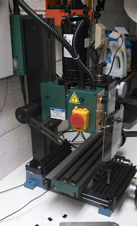
In the above picture you can just see the end of a foil shim sticking out between the base and column.
http://www.littlemachineshop.com/products/product_view.php?ProductID=4483&category=
It has a column with thicker walls than stock with bolts via four bolts to the bed. It's much superior. You have to use shims to adjust both X and Y alignment. You can view the two adjustment separately, and simply sum the shim on the shared corner. For example, if you need 0.001" of shims on the front of the column and 0.002" of shims on the right of the column, then the left back corner wouldn't have any shims, the left front corner would have a 0.001" shim, the left right corner would have a 0.002" shim, and the right front corner would have a 0.004" shim.
I upgraded the mounting bolts to grade 12.9 M8x40 socket head cap screws which are 5mm longer and have more thread engagement. I used a torque wrench to tighten the bolts to make my readings consistent between adjustments, using 16.5 ft/lbs (200 in/lbs) with silver anti-sieze on the threads.

Mill: DRO
Please read the complete article:
http://benchtopmachineshop.blogspot.com/2017/04/mill-touchdro.html
One of the biggest problems with the X2 is the amount of backlash in all the axis. Instead of trying to lessen the backlash I simply installed digital scales with remote displays on the X and Y axis (Z is being installed this weekend) to act as a poor man'd DRO. Since they read the table's position directly, you can pretty much ignore the backlash present. The X scale is mounted on the back of the table with a protective aluminum shield over it. If you're using the tilting column then you'll lose Y travel unless you offset the scale's pickup to one side. I originally did that by extending the aluminum channel past the table and mounting the end of the scale in it.

However, that problem goes away with the solid column upgrade. The Y scale in mounted to the base on the left of the mill. The base's sides have a slight angle to them, but that doesn't matter when mounting the scale so long as it remains parallel to Y axis. I've found the table itself shields the scale sufficiently.


This is absolutely, positively the first upgrade which should be done to the mill. I don't really understand how someone can use an X2 without it.
Lathe: Carriage Lock and Way Protector
I have a Grizzly 7x12 mini lathe, which is just a repainted Sieg C2 lathe. If you're not looking for super accuracy you can start working with it right out of the box. It's biggest drawback is lack of a carriage lock. Locking the half huts helps, but there's still a lot of play, and it will adversely affect any facing or parting operations. I think one of the first things to do is add one. There are plenty of designs out there, but I think the best ones clamp the carriage down onto the ways.
The one I made bolts to the mounting holes for the follower rest on the left of the carriage. You can't see it, but the center socket cap screw threads into a T shaped piece which rides under the ways. Aside from the screw there is also a locating pin between the two pieces to keep it from spinning when tightening or loosening. One half turn of the screw goes from free to locked. If it gets too annoying on the left of the carriage I'll drill and thread holes to move it to the right, but I hate threading so it'll need to get fairly annoying. You can also see the added way protector, which is just the bellows ways cover from a X2 mini mill cut to size.

UPDATE: I added a lever to make locking it easier. I also glued a magnet in place to hold the lever in place and accessible until needed.

Subscribe to:
Posts (Atom)