First off, all credit to Yuriy Krushelnytskiy of http://www.yuriystoys.com/.
One of the biggest problems with the X2 is the amount of backlash in all the axis. Instead of trying to lessen the backlash I installed TouchDRO on all three axis. Since they read the table's and head's position directly, you can pretty much ignore the backlash present.
While poking around the internet for information on the X2 mill, I stumbled on Yuriy's blog. What really intrigued me was his DRO application for the Android: http://www.yuriystoys.com/search/label/DIY%20DRO%20Project
He was using iGaging digital scales, which most X2 owners end up using when installing DROs, connected to an Arduino, which interfaced with an Android via Bluetooth. The DRO app he wrote took the input from the digital scales and displayed it in a nice interface. Just that alone had my attention since the included iGaging remote LCD displays were a little hard to see. However, since all the work is being done in software, it'll be easy to add new features to the DRO in the future. Additionally, since it's open source, you can always add a must have feature yourself. Now that Androids have gotten cheap enough and powerful enough, it makes a lot of sense to do in software what traditional DROs did in hardware. Doing it in software is just much cheaper and much more flexible.
If you have the tilting column, the X scale needs to be offset not to lose travel from the read head hitting the column pivot, the aluminum L channel being used as a chip shield makes a pretty convenient offset mount. With the solid column mill the X scale can be mounted centered.
I used a 2" aluminum angle completely cover the scale, cutting down one side so it fits on top of the chip shield. Without it, tiny chips can get inside the read head and cause reading jumps.
 |
| Offset X scale for column pivot clearance. |
 |
| Centered X scale on solid column mill. |
 |
| Chip cover in place over the scale. |
The Y scale in mounted to the base on the left of the mill. The base's sides have a slight angle to them, but that doesn't matter when mounting the scale so long as it remains parallel to Y axis. I've found the table itself shields the scale sufficiently.
 |
| Y scale mounted. |
Once I installed the gas spring and removed the old torsion spring, installing the Z axis DRO was super easy. I removed the ruler on the left side of the column a while ago, since it was so course it was pretty much useless. The 12" iGaging digital scale was the perfect length to screw right into the holes left by the ruler. I then quickly fabricated a bracket to connect the scale's reader to the threaded hole on the head which used to hold the ruler's indicator. Perfect.
 |
| Z scale mounted using existing threaded holes. |
At first I had tried using a prepackaged optical sensor for Arduino (available on Amazon), but switched to a Hall effect magnetic sensor since they're easier to use and for this application tend to be just as accurate. I was able to buy them already mounted on a psb with a LS393 comparator (http://www.amazon.com/dp/B009M86TFG/). The comparator allows you to have an essentially digital signal with it either on or off.
I
already have a belt drive installed, so I drilled two holes at opposite
ends of the top pulley and JB Welded in small neodymium magnets. The
top of the Hall effect sensor psb was covered with epoxy putty to
protect it from swarf. Then it was attached to the pulley cover using
foam tape and a mounting screw. The sensor itself hangs over the back of
the cover and directly over the path of the magnets.
For the Arduino I bought the Leonardo model which comes without headers,
since I like soldered connections. However, I learned the hard way the
app does NOT like the Leonardo. The app would connect, and then
immediately lose connection. Once I switched from the Leonardo to the
Uno R3 everything started working beautifully. The Uno R3 comes with
headers, so I needed to cut them off and de-solder the pins so I could
solder the leads in place. | |
| Magnets on the pulley. The black sections were for the optical sensor. |
 |
| The Hall effect sensor covered with epoxy putty and mounted on the pulley cover. |
 |
| Uno R3 with the headers and pins removed. |
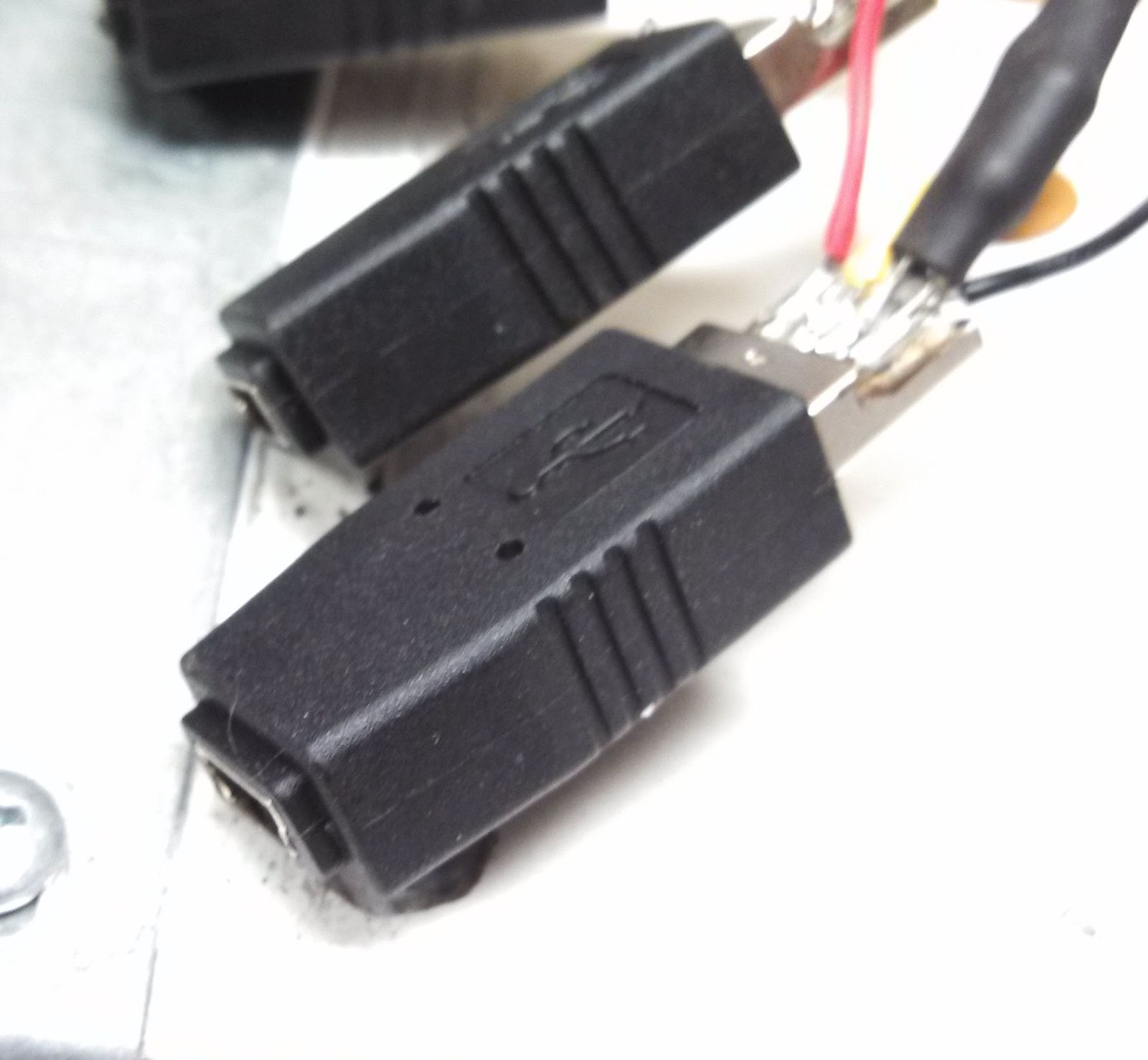 |
| Mini B USB adapters. |

Adapters wired to the Arduino.
I used a 3.5mm stereo headphone jack for the tachometer interface. If I get around to repackaging the Arduino I'll change it to another interface since the 3.5mm jack will short power to ground as the connector is inserted or removed, so you need to power down the Arduino before doing so. It's not a show stopper, but it is annoying. I've hot glued the connector so it can't accidentally pull out while in use. A 10K pull down resistor needed to be added to the tach sensor input.
I bought a small project box from Radio Shack, and aside from the very annoying issue with the Leonardo, the hardest part was installing everything inside the box. I machined slots in for the USB adapters to stick out through. I wedged them in there and glued them in place with epoxy. I also cut a hole for the USB cable which will provide power. To mount the Arduino I secured a thin piece of wood in the bottom of the project box, which the Arduino screwed to.
 |
| All packaged up. |
I then used Sugru to make the USB connectors look pretty, enclose the USB power cable, and provide it with strain relief. If you haven't used it before, Sugru is a really useful thing to have in your tool box. It comes in little packets and it's silicone rubber which sticks to most things and is moldable for 30 minutes after opening, and cures in 24-48 hours.
 |
| Sugru. |
 |
| The project box with Sugru added. |
After that the USB cable was hot glued into the USB jack on the Arduino, the unit was tested again, and then the top was screwed in place. Magnets were glued to the box and the box mounted on the back of the column. It draws its power form a Motorola cell phone charge.
 | |||||||
| All packed up and ready to go. |
There were issues with TouchDRO reading 20-40 times too low on the tachometer. After some time spent on the TouchDRO Google+ development forum I changed the Arduino sketch to one being developed by Ryszhard (http://www.rysium.com/rysium.docs/) and the tach immediately started working. I checked its readings against my laser tachometer and they match to within 20 RPM.
For my readout I'm using a 10" non-widescreen tablet, as I find the non-widescreen format works better for a DRO. This has been one of the best upgrades I could have possibly done and made the mill so much easier and nicer to use. I cannot recommend it enough, and I would never go back to not having one.