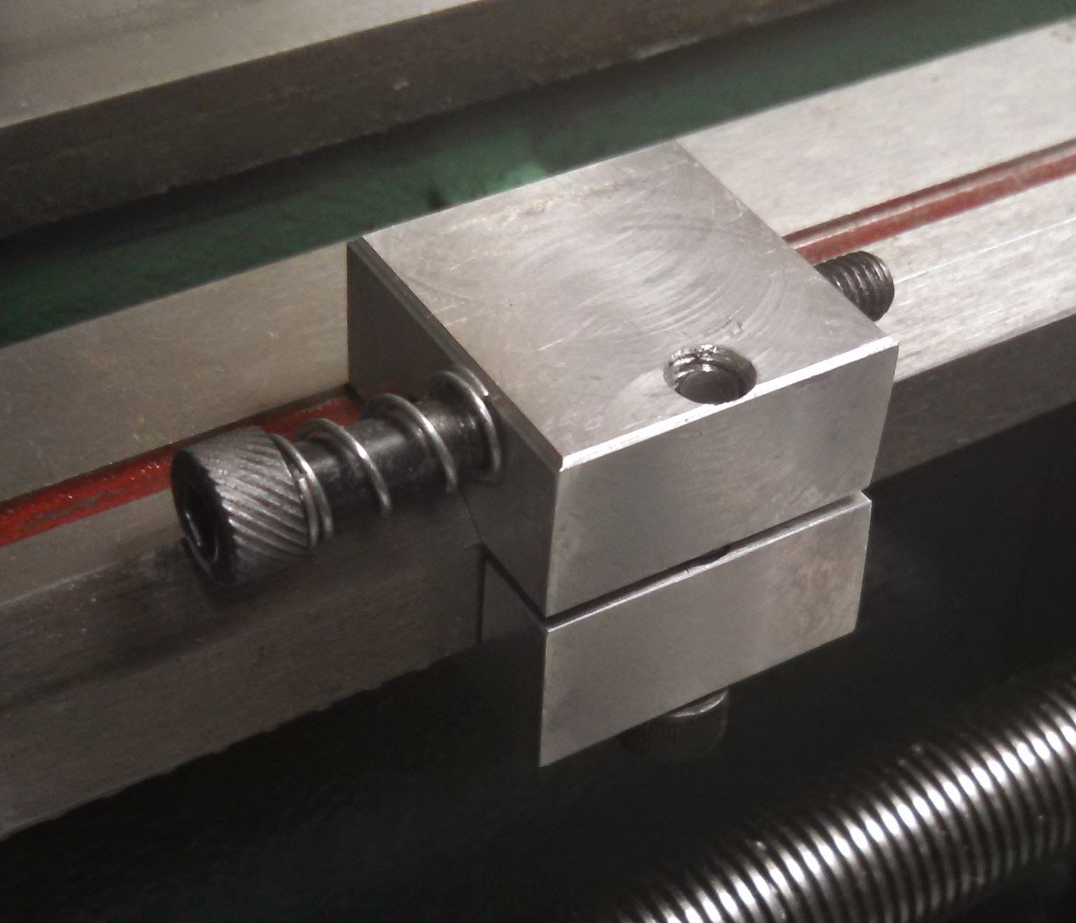
Decided to make a carriage stop for the lathe. Even though I have the DRO, it's nice to just move the carriage until it stops instead of to a number. It was just made from aluminum, and the screw to tighten it was moved to the bottom so it wouldn't interfere with the ways protectors I have installed. Currently you need an allen key to tighten/loosen it, and I probably won't change that since I don't see myself using it all that much.
Wednesday, February 25, 2015
Lathe: Compound Lock and Gib
The compound slide gib is not nearly robust enough for the forces you can see, especially when parting and threading. I've seen the whole compound rotate over on the gib when the parting blade jammed. To remedy this I added to both add a gib lock and to add an extra gib set screw.
I removed the top of the compound and clamping it in the mill and drilled and tapped two extra holes located exactly between the existing set screws. After modifying the gibs (http://benchtopmachineshop.blogspot.com/2015/01/lathe-gibs.html) I put a dog nose on a M4 SHCS and installed it in the middle set screw hole. Now the compound has more support overall and I can easily lock it in place.
![]() |
| Extra gib set screws with the gib lock right in the middle. |
Monday, February 9, 2015
Mill: Screwless Precision Vise
Please read the complete article:
http://benchtopmachineshop.blogspot.com/2017/04/mill-vises.html
One of the biggest annoyances using the precision screwless vise was loosening the jaw and accidentally unscrewing it from the T bracket which holds the cross bar that hooks into the base. After having it happen it again in the middle of a project I took the screw which connects the jaw to the T and turned it smooth starting 5 threads from the end.
I then ground a flat on the T right where it threads onto the screw. I then assembled the vise, threaded the screw into the T, and peened the flat to capture the screw. Now, no more accidentally unscrewing it.
http://benchtopmachineshop.blogspot.com/2017/04/mill-vises.html
One of the biggest annoyances using the precision screwless vise was loosening the jaw and accidentally unscrewing it from the T bracket which holds the cross bar that hooks into the base. After having it happen it again in the middle of a project I took the screw which connects the jaw to the T and turned it smooth starting 5 threads from the end.
![]() |
| Middle section of screw turned smooth. |
I then ground a flat on the T right where it threads onto the screw. I then assembled the vise, threaded the screw into the T, and peened the flat to capture the screw. Now, no more accidentally unscrewing it.
Wednesday, February 4, 2015
Bandsaw Vise
I wanted to add a bandsaw to my workshop, but because of limited space I needed something small. The Grizzly G8692 portable bandsaw and stand were the right size and definitely the right price.
The big problem was the included vise. It was too flimsy and stood way too far away from the blade. If you're never cutting a piece less than 12" long it might work, but it's utterly useless cutting anything short.
The first thing I did was move the vise toward the saw by 1.5". That's as close as I could get it without the saw hitting the vise. At this distance the saw cuts slightly into the vise base, but that's fine. The vise's quick release lever needed to be slightly shortened so it wouldn't interfere with the saw. The bolt also interfered with the saw so I switched it out for a socket head cap screw on which I turned the head down to a smaller diameter.
Then I cut sections of 2" wide 1/8" steel plate to extend the vise jaws all the way to the edge of the saw blade. In addition, the fixed saw got an extra 1/8" plate bolted to its back to help stiffen it more. The plates and jaws were welded together at their edges. A brace was also added between the fixed jaw and the base.
Since the moving jaw on the bandsaw vise is on a pivot, if what you're clamping doesn't extend beyond the pivot, the whole jaw will rotate and won't clamp. To fix this I drilled a 1/2" hole in the fixed jaw on the end of the vise opposite the saw, and welded a 5/16" nut to the outside of it. I then took a piece of 5/16 threaded rod, red Loctited two nuts onto the end, turned the other end flat and chamfered it, and then threaded it through nut. Now I can quickly thread the rod through to space the moving jaw correctly.
It's still not perfect, but it's very usable now.
The big problem was the included vise. It was too flimsy and stood way too far away from the blade. If you're never cutting a piece less than 12" long it might work, but it's utterly useless cutting anything short.
The first thing I did was move the vise toward the saw by 1.5". That's as close as I could get it without the saw hitting the vise. At this distance the saw cuts slightly into the vise base, but that's fine. The vise's quick release lever needed to be slightly shortened so it wouldn't interfere with the saw. The bolt also interfered with the saw so I switched it out for a socket head cap screw on which I turned the head down to a smaller diameter.
Then I cut sections of 2" wide 1/8" steel plate to extend the vise jaws all the way to the edge of the saw blade. In addition, the fixed saw got an extra 1/8" plate bolted to its back to help stiffen it more. The plates and jaws were welded together at their edges. A brace was also added between the fixed jaw and the base.
![]() |
| 1/8" steel reinforcing plates welded into place. |
![]() |
| Brace welded in place. |
Since the moving jaw on the bandsaw vise is on a pivot, if what you're clamping doesn't extend beyond the pivot, the whole jaw will rotate and won't clamp. To fix this I drilled a 1/2" hole in the fixed jaw on the end of the vise opposite the saw, and welded a 5/16" nut to the outside of it. I then took a piece of 5/16 threaded rod, red Loctited two nuts onto the end, turned the other end flat and chamfered it, and then threaded it through nut. Now I can quickly thread the rod through to space the moving jaw correctly.
![]() |
| Threaded rod in place, screwed all the way out. |
![]() |
| Threaded rod adjusted in to space the moving jaw. |
It's still not perfect, but it's very usable now.
Tuesday, January 27, 2015
Lathe: Gibs
I finally took the time to modify my lathe's cross slide and compound gibs the same way I did my mills: http://benchtopmachineshop.blogspot.com/2013/06/mill-gibs.html
The big difference was the lathe's gibs use a 60 degree angle versus the mill's 55 degree angle.
In addition, I also added two extra set screws on both the compound and cross slide in order to give it some extra rigidity. In the picture of the cross slide's set screws you can see I used three different type. The two stock ones were used due to clearance issues, the hex head was used because it's always behind the DRO read head and the hex head allows for adjustment, and the two socket head cap screws were used due to ease of adjustment. It looks a little sloppy, but aids in usability.
After cutting the pockets I reassembled everything with a generous amount of Mobil Vactra way oil on the gibs and ways. While I expected an improvement in the feel, I didn't expect the huge improvement I actually got. Even though they're snug and there isn't any play, both compound and cross slide move very smoothly and easily now. The difference is amazing.
The big difference was the lathe's gibs use a 60 degree angle versus the mill's 55 degree angle.
In addition, I also added two extra set screws on both the compound and cross slide in order to give it some extra rigidity. In the picture of the cross slide's set screws you can see I used three different type. The two stock ones were used due to clearance issues, the hex head was used because it's always behind the DRO read head and the hex head allows for adjustment, and the two socket head cap screws were used due to ease of adjustment. It looks a little sloppy, but aids in usability.
After cutting the pockets I reassembled everything with a generous amount of Mobil Vactra way oil on the gibs and ways. While I expected an improvement in the feel, I didn't expect the huge improvement I actually got. Even though they're snug and there isn't any play, both compound and cross slide move very smoothly and easily now. The difference is amazing.
![]() |
| The menagerie of set screws. |
Friday, January 23, 2015
Lathe: Leadscrew Handwheel
One of my biggest problems with the lathe is the carriage hand wheel isn't very precise for Z axis movement; it's hard to always stop it exactly. I don't like using the compound for fine Z axis movement since while carriage has a DRO on it, the compound does not. Also, I want to remove the compound eventually and replace it with a solid block of steel; the compound reduce rigidity of the system and I only use it for threading operations.
I know if I could attach a hand wheel to the leadscrew then I could put the leadscrew in neutral, lock the half nut, and slowly turn the leadscrew to move the carriage.
I decided to extend the leadscrew shaft past the pillow block to make a mounting point for the hand wheel. I removed the leadscrew, chucked it in the lathe, and drilled a hole in the end. It's already been center drilled which made things easier. I then took 1/2" steel rod (stolen out of an old ink jet printer) and turned down the end of it to the same size as the new hole in the leadscrew, making sure to leave a precise shoulder. After mating the rod and leadscrew together I welded around the seam, and then turned the weld bead down in the lathe.
I bought a hand wheel from Amazon: http://www.amazon.com/dp/B00EDKIK9G. Since it had a 10mm bore I turned the lead screw extension down to 10mm. I took the hand wheel and drill and tapped three holes in it to accept set screws. After positioning the wheel where I wanted it on the shaft I installed the first set screw fairly hard in order to mark the shaft well. I then remove it and the hand wheel, turned an extended nose on the set screw, and drilled a shallow hole at the marked spot on the shaft. I then reassembled everything and made sure the set screw seated into the hole. I then installed the other two set screws.
It ended up working really well and I now have easy fine Z axis adjustment.
I know if I could attach a hand wheel to the leadscrew then I could put the leadscrew in neutral, lock the half nut, and slowly turn the leadscrew to move the carriage.
I decided to extend the leadscrew shaft past the pillow block to make a mounting point for the hand wheel. I removed the leadscrew, chucked it in the lathe, and drilled a hole in the end. It's already been center drilled which made things easier. I then took 1/2" steel rod (stolen out of an old ink jet printer) and turned down the end of it to the same size as the new hole in the leadscrew, making sure to leave a precise shoulder. After mating the rod and leadscrew together I welded around the seam, and then turned the weld bead down in the lathe.
![]() |
| Leadscrew extension sitting beyond the pillow block. |
It ended up working really well and I now have easy fine Z axis adjustment.
![]() |
| I left the shaft slightly longer than necessary to allow for future adjustments. |
![]() |
| The new hand wheel set screws are visible. |
Wednesday, December 17, 2014
Lathe: Tailstock Setscrew
The lathe tailstock uses a set screw to hold alignment while tightening the bolt underneath the tailstock. The stock set screw uses just a slotted head and its dog point isn't very well made, so when you tighten it the tailstock tends to move out of alignment. I replaced the stock screw with a socket head cap screw, and inserted a ball bearing in front of the new screw. This allow the set screw to apply much more even and stable pressure as it's being tightened.
Also, make sure you don't have any paint over spray on the tailstock's mating parts.
Subscribe to:
Posts (Atom)