NOTE: This turned out to be, by far, the most difficult upgrade I've done yet. A lot of issues came up and a lot of things went wrong. I ultimately ended up destroying eight bearings and a countershaft before I found the correct procedure, and this article only describes that final, correct procedure.
I've wanted to upgrade the bearings in my lathe for a while. Deep groove ball bearings aren't ideal for a lathe since they can't handle much preload, and preload is necessary for a rigid spindle.
A popular upgrade for the mini lathe are tapered roller bearings (TRBs), with people often using cheap car axle bearings. The problem is those axle bearings have a max runout of 0.001" which is pretty bad. You can buy higher TRBs (minimum grade C or P5) but they're not easy to find and can be quite expensive. Additionally, TRBs are very sensitive to preload, and have a very small window of acceptable preload. Finally, TRBs are 1.5mm deeper than the stock bearings, which requires some modifications of the lathe.
 |
| Tapered roller bearing cutaway. |
However, I decided to go with angular contact ball bearings (ACs) like I did in my mill (
http://benchtopmachineshop.blogspot.com/2015/05/mill-angular-contact-bearings.html). Unlike deep groove ball bearings, ACs are able to take both axial and radial loads. ABEC-3 precision 7206 ACs (roughly equal to TRB class C or P5) are fairly readily and cheaply available. I usually buy SKF ones at about $25 each. They're also the same dimensions as the stock bearings, which make it a direct swap. ACs are much more tolerant of a wide range of preloads, which makes setting the preload much easier and more forgiving than with TRBs. While ACs are less rigid than TRBs, for a machine as small as a mini lathe it shouldn't matter at all.
 |
| Angular contact ball bearing cutaway. |
On a related note, you may have seen instruction for installing ACs on the mini lathe on other sites. The problem with those instructions is they have you pressing in the bearing through the rolling elements. In other words, you're applying pressure to the inside race in order to press the outside race into its bore. You should never do this. The manufacturers will always tell you not to press the bearing through the rolling elements because, while the bearings can handle high dynamic loads, the high static load from pressing can damage both the races and the balls themselves, greatly reducing the life of the bearing.
Since I was already pulling the spindle out, and on the mini mill and mini lathe the spindle cannot be removed without damaging the bearings, I decided now would be a good time to upgrade to a 4" diameter spindle as well. The new spindle will allow me to run 4" chucks without an adapter plate and give me a larger spindle bore. I've run into capacity problems with both in the past, so it will be very welcome. You can buy the spindle directly from
http://www.amadeal.co.uk or you can buy it slightly cheaper through their eBay store if you're in the USA.
Since the spindle is coming out it's a good time to upgrade the spindle gear from plastic to metal (available at
http://www.arceurotrade.co.uk) since if it broke the spindle would need to be removed which would destroy the bearings. The countershaft gear will remain plastic to act as a mechanical "fuse" and to also keep the gear noise down.The countershaft needs to come out to replace the spindle gears, so it's a good time to upgrade the countershaft bearings and change the chuck side countershaft bearing from shielded to sealed since it's exposed to a lot of contamination.
The new spindle bearings are open, so I need to prevent contamination. New bearing covers were made from aluminum to house standard oil seals; the chuck side is 48x58x7mm and the gear side is 40x55x5mm. Since I'm using grease lubrication without a pressure differential the garter springs were removed from the seals to reduce friction. The bolt holes were marked using grub screws in the head and Dykem on the covers. A tight seal wasn't needed for the inside face of the bearings, so I fabricated two 42x62mm shims from 0.004" spring steel to fit between the bearing and its seat. If you don't want to use separate seals, you can use the SKF sealed AC bearings like I used in my mill, but they're significantly more expensive.
 |
| Bearing covers marked for the bolt holes. Only two are used for the lathe. |
 |
| Dykem (mostly) removed and oil seals installed. |
 |
| Spring steel shim. |
The new spindle's bearing seats diameters were large enough to make the bearings a very tight press fit, which would make setting the preload quite difficult. It was chucked in the lathe and I carefully sanded the bearing seats until they were a mild press fit, the back bearing more so than the front bearing.
The spacer at the back of the lathe that goes between the rear bearing and the lock nuts is made from Delrin, which is not a suitable material for the oil seal to run on. However, that area isn't really prone to contamination, so the oil seal doesn't need to actually seal against the spacer. So, I made a spacer from aluminum just slightly smaller than the ID of the oil seal. It ended up being 31.5mm long with an OD of 38.7mm. I could have just modified the Delrin seal, but it was easier to just make a new one. Because the new spindle dimensions are slightly different from old one, the spacer had to be relieved on the bearing side for clearance.
 |
| Aluminum spindle spacer with relief. |
I also purchased two new spindle nuts and iteratively faced their sides to get them as close to square and parallel as I could. They'll help insure the new bearings are preloaded as evenly as possible. Again, because the new spindle dimensions are slightly different from old one, the lock nut which tightens against the gear had to be relieved on one side for clearance.
 |
| Lock nut faced and relieved. |
Finally, the spindle spacer that goes between the big gear and the bearings needs to be metal instead of plastic, since it's used to pull the spindle up through the bearing, so it was remade in steel using the left over spindle spacer from my mini mill's belt drive upgrade.
 |
| Stock plastic spacer on left and new metal spacer on right. |
I pulled the headstock off, put it in the vise, and hammered out of the old spindle with a rubber mallet. The spindle pulled the chuck side bearing out with it. The back bearing was knocked out with a punch and hammer. The countershaft snap rings were removed and the shaft tapped out of the bearings, and the countershaft bearings themselves tapped out of the headstock.
There are four threaded holes on the headstock for grounding wires. Since I wanted a way to apply more grease to the gears without removing the headstock, I drilled out the two center holes to 1/4" and countersunk the outside of them. This gives me enough room to apply grease to the gears with a syringe.
 |
| Headstock in vise about to have the spindle removed. |
I've already fabricated a bearing press for my mill, and the mill and lathe use the same bearings. Since I can't press a bearing through the rolling element, the order in which they're installed is very important, and made it up grade fairly tricky. I also made sure to lightly oil both the spindle bearing seat and bearing bore.
 |
| Bearing press with the mill's old spindle and bearing. |
First I pressed the bearing (thick side of inner race facing out) into the chuck side of the headstock. Then the bearing cover with the oil seal installed was greased and placed over the spindle, and the back of the spindle inserted through the bearing. Then, the metal spindle spacer and the large gear were placed on the spindle. Finally, the spindle was drawn up through the bearing using my bearing press and a piece of PVC as a spacer. and then the spindle was drawn up through the bearing, being sure to only place force on the bearing's inner race.
 |
| Pressing bearing into headstock. |
 |
| Just starting the draw the spindle up through the bearing. You can see the new oil seal installed . |
 |
| Spindle being drawn up through the bearing. Note the large gear in place. |
 |
| Gear in place on spindle. The key hasn't been installed yet. |
Once in place, I slipped the end of the key through the large gear, and then tapped it down into the gear, and then into the spindle using a punch. I made sure to properly support the spindle so the bearing wasn't taking any of the hammering. Then I placed the gear spacer, small gear, and plastic spacer on the spindle.
I noticed the final spacer didn't seem to give enough clearance between the small gear and where the inner race of the bearing was going to be, so I sanded down the plastic spacer until it was only 7.1mm thick.
The next part was a little tricky. I had to press the back bearing in, but I had to make sure the press was working against the headstock and not the spindle, since that would apply force through the bearing I just installed. Using some spare washers and bolts, I braced the spindle's mounting flange against the headstock's body, this way any force would be directed into the headstock and not the bearing. AC bearings have play in the inner ring before being preloaded, and I made sure the spindle flange was as far away from the headstock as that play allowed. This is critical to accurately preloading the bearing later. Once the bracing was in place I dropped the shim in place and pressed the bearing in. Note, I designed my press to push contact both the inner and outer race of the bearing. I greased up both bearings and oil seals, and screwed the bearing covers into place.
 |
| Spindle braced against headstock. |
 |
| Pressing the back bearing into place. |
Quick note on grease. After doing a LOT of research, I found that Kluber NBU 15 grease is awesome for spindle bearings. However, for a low speed, relatively low precision spindle like my mini lathe's the grease isn't all that critical. So instead of spending the money on Kluber, I used Bel-Ray Waterproof Grease since I already had it on hand and think rather highly of it.
Here I ran into a problem. The countershaft is a tight press fit on both bearings, which is unnecessary and makes installing it needlessly difficult. I sanded down the chuck side of the countershaft until it was a slip fit in the bearing (I ruined one countershaft by sanding it too much). I pressed the back side bearing onto the countershaft, and then installed it in the headstock. I lubed the headstock gears with the same Bel-Ray grease used for the bearings since it's plastic safe and pretty tenacious.
When tightening down the nut to preload the bearing, I need to account for two things: first the amount of force it takes to slide the bearing on the spindle, and the amount of torque it takes to place the proper preload on the bearings. To find the force needed to slide the bearing on the spindle I tightened the lock nut down by hand, took my torque wrench with my lock nut adapter, and kept slowly increasing the torque until the nut started to turn. In my case it was 105 in/lbs. That's higher than I would prefer, and if I change the bearings again I'll reduce the spindle's rear bearing seat a little more.
 |
| 32mm socket ground down with an angle grinder to fit the spindle lock nut. |
Knowing I wanted about 125 pounds of preload, using the calculator at
http://www.engineersedge.com/calculators/torque_calc.htm gave me about 23 in/lbs torque for that clamping force (when using a nut to preload bearings, clamping force is the same as preload force).
Adding the two values together gave me 128 in/lbs, which is what I tightened the lock nut to, and then made witness marks so I could re-tighten it to the exact same spot if I needed to remove it. Then I installed the second lock nut, snugging it against the first one, but not overly tight. It's only needed to prevent movement.
As you may have noticed, when you tighten the lock nut, you are transmitting force through the rolling element of the front bearing. Unfortunately, I haven't found a way to avoid it in this case. If the rear bearing is a slip fit, then the spindle can turn inside the inner race and caused galling. Therefore I try and make the press fit as light as possible, to make the force transmitted through the rolling element as little as possible. Since 7206 bearings can take a heavy preload of over 220 pounds and have a static load rating of approximately 3,200 pounds, hopefully this doesn't reduce their lifespan all that much.
 |
| Front of headstock, ready to go. |
 |
| Back of headstock with the spindle extension attached. |
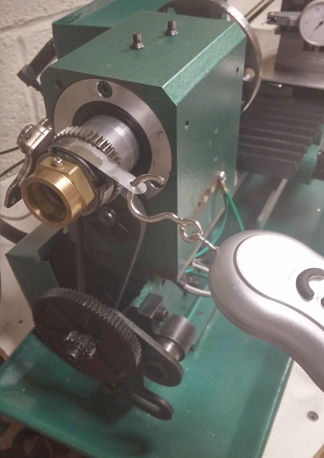
To check if I got the preload right, I measured the breakaway torque, meaning the amount of force required to make the spindle start to turn. This can be fairly easily calculated using a thin feeler gauge, a strong magnet, and an scale. You fix the end of the shim to the spindle using the magnet, measure the diameter of the spindle in inches where it's attached, hook the scale to the shim, wrap the shim around the spindle as far as it'll go, and then pull on the scale and see how much force in pounds is required to start turning the spindle. If you multiply that by the radius you get the breakaway torque in in/lbs. For example, I measure at the lock rings, which have a radius of 0.815". My breakaway force measured at 1.25lbs. Therefore, the breakaway torque was 1.02 in/lbs. For a mini lathe or mini mill using AC bearings, about 1 in/lbs is good, and I'd estimate a range of 0.6-1.5 in/lbs being acceptable.
Since grease can effect the breakaway torque I'll turn the spindle in the opposite direction I'm going to measure and then turn it back just slightly and then measure. I've found this technique creates a "dead spot" in the grease and almost completely eliminates its friction.
 |
| Shim in place, wrapped around the spindle, and just starting to pull with the scale. |
|
|
|
|
|
I ran in the new bearings starting at 750 rpm until the temperature was stable for 10 minutes, and then increased rpm by 250 and repeated, until I hit the max speed of the lathe. The temperature was monitored on the top of right next to the front bearing using a IR thermometer which I pressed against the headstock. If the temperature stays under 60* C then the preload is fine. On mine the temperature barely even reached 45* C.
Even when properly preloaded, I had 0.0005" of lateral play with light-moderate pressure at the end of the spindle. Regardless of the amount of preload that play remained, therefore I believe it's inherent in the design of AC bearings. However, I'm not overly worried about it, as it's only going to reduce my cut depth by about 0.00025", which should be fairly easy to account for.