Sunday, April 2, 2017

Lathe: Power Cable

I really dislike how the power cable goes through the motor cover and lathe bed to get to the control box. It means whenever I want to remove the motor cover I also need to remove the control box to disconnect the power cable. It makes much more sense to me to simply connect the power cable directly to the control box.

Power cable in place and bolted to the control box.

With the chip tray removed there was plenty of room to route the power cable under the lathe and to the bottom of the control box. I drilled a 1/2" hole and made a bracket out of aluminum which was riveted into place. The old cable hold down bracket was then used to bolt the cable to it.

Lathe: Chip Tray

I hate the chip guard on my lathe. It's not shallow enough, and the chuck can easily grab the chips and throw them around. I've ended up with chips in my hair too many times because of it. So I removed it. The motor cover has vent holes on its end, so I formed a piece of aluminum to cover it and deflect chips.

Aluminum chip deflector riveted in place.
While I was at it I also removed the chip tray. It serves absolutely no propose and just made things harder to clean up. It was fairly easy to remove the tray and reinstall the legs themselves.

Both chip guard and chip tray removed.

It hasn't been any harder to clean up, and it definitely makes it easier to work with and to clean up afterward. The only downside is I'm still looking for a good place to put the DRO control box.

Monday, March 20, 2017

Lathe: QCTP Rotation


I have a 0XA QCTP installed on my mini lathe. Instead of using the included nut to bolt it to my carriage I used the handle off the stock tool post. This allows me to quickly rotate the QCTP into a new position, an option which I use a lot to either provide clearance or give the tool bit a better angle.


Tool post in rotated position.


Saturday, March 18, 2017

Lathe: Gear Reduction Pulleys

I realized I never used the high speed on my mini lathe, and I really needed a lower speed on there than what I had for parting and knurling. In addition, the mini lathe belt is a proprietary part which I'm not a fan of.

There are a lot of sellers on eBay selling ratio reduction pulleys for the mini lathe. They'll drop the low speed to 700 RPM and high speed to 1800 RPM with an increase in torque and lower low speed.

I bought the cheapest one I could find expecting it to need modification to be usable, and it did. I needed to turn the large pulley down to 10mm wide to fit. I then needed to cut a keyway in the motor pulley. However, once I was done they fit nicely and use a standard xl (163xl037) belt which is easily available on Amazon.

Pulleys and belt in place.

In low speed it's now usable down to about 150 RPM which is a really nice change from before, and should really help parting and knurling. I may eventually experiment with the ratio and go up a tooth on the motor.

Wednesday, March 8, 2017

PWM Control Notes

Peak Voltage:
The KB PWM control I use produces a peak voltage of 160VDC which is very rapidly switched on and off to produce a lower average voltage. I was worried about the 110VDC motor being hit with 160VDC, but after research I found if the frequency is high enough, then it doesn't really matter (assuming the peak voltage isn't absurdly high).
"As long as the PWM frequency is fast enough, it's average voltage is what counts. No, the average PWM voltage should not exceed the motor's rated voltage, at least not for long. This is no different that applying a DC voltage to the motor.

Using a high voltage supply and then less than 100% PWM to compensate is a perfectly legitimate way to run a motor, again, as long as the PWM frequency is fast enough. In effect you are creating a switching power supply that converts the high voltage to the lower one used to drive the motor. It may not look that way because the induction of the motor windings are a integral part of this power supply.
"

- Olin Lathrop

The things which kill a motor are overloaded bearings, bearing run too fast, brush arcing, and damage from overheating. None of those is really a result of voltage, and a high frequency PWM drive will actually allow the motor to run cooler while producing more torque.


Adjusting Max Voltage:
The high frequency a PWM motor control outputs to the motor can leave a digital multimeter confused or inaccurate if you're trying to measure the max volts, while I've found using an analog multimeter will respond accurately to the PWM output.

If you have a digital multimeter which can read duty cycle and you know the peak voltage (160VDC in case of the KBWS using 115VAC), you can multiply the duty cycle by the peak voltage to get the average voltage, which is what the motor should see. 

To set the max volts to 110VDC for the mini lathe and mini mill's motors I first used a analog multimeter to set the max output to 110VDC. Then to double check I calculated the motor RPMs from the spindle RPMs since I knew the gear ratio; the lathe has a 5000 RPM motor while the mill has a 6000 RPM motor.


Tuesday, February 28, 2017

Lathe: Headstock Bolt Torque

The mini lathe's headstock is a very poor design. Tightening it to the bed puts a lot of force on the channel in the headstock's bottom which mates to the bed's prism, and the outer side of the channel is not well supported. Even worse, a square relief was cut in the channel which concentrates the stress at the corners of the relief. Ultimately, if you tighten the headstock down tight, you run a good chance of cracking it.

After some research by Grizzly, a recommended torque of 96-144 inch pounds is recommended for the bolts, and I would stay toward the bottom end of that. I torque them to 102 inch pounds, or 8.5 foot pounds.

Crack originating from inside corner.

Bearing Preload

Bearing preload is critical for machine tool spindles since it keeps the spindle rigid, especially under load. It's the amount of compressive force placed on the bearings at rest, and is usually expressed in pounds force or newtons force. For example, my mill spindle has approximately 100 pounds of preload.

High end machine tools use angular contact (AC) bearings which are ground such that, when clamped together back to back, automatically provide the required amount of preload. Unfortunately, the design of our mini lathes and mini mills makes setting the preload extremely difficult since setting it via the spindle nut is very imprecise, and you're also fitting the press fit of the bearing on the spindle.

Now that I've replaced my spindle bearings quite a few times, I've found several different ways to check the bearing preload. In practice I'll usually end up using all of them as double checks.

1. Calculate the torque required for the desired clamping force. I use the this http://www.engineersedge.com/calculators/torque_calc.htm online calculator. The problems with using torque is you need to account for the addition force necessary to move the bearing's inner race on the spindle and the amount of torque needed can change while tightening the nut.

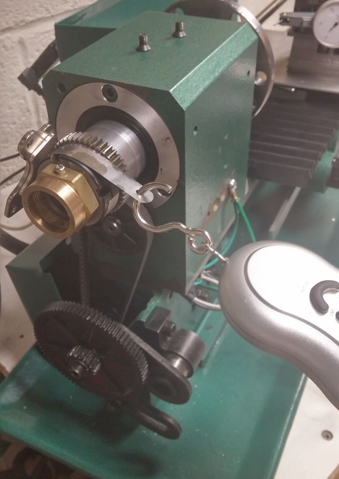
2. Check the breakaway torque, meaning the amount of force required to make the spindle start to turn. This can be fairly easily calculated using a thin feeler gauge, a strong magnet, and an scale. You fix the end of the shim to the spindle using the magnet, measure the diameter of the spindle in inches where it's attached, hook the scale to the shim, wrap the shim around the spindle as far as it'll go, and then pull on the scale and see how much force in pounds is required to start turning the spindle. If you multiply that by the radius you get the breakaway torque in in/lbs. For example, I measure at the lock rings, which have a radius of 0.815". My breakaway force measured at 1.25lbs. Therefore, the breakaway torque was 1.02 in/lbs. For a mini lathe or mini mill using AC bearings, about 1 in/lbs is good, and I'd estimate a range of 0.6-1.5 in/lbs being acceptable. If you're using tapered roller bearings, then a breakaway of a little under 10 in/lbs is good (which also illustrates the much higher friction inherent in tapered roller bearings).

Since grease can effect the breakaway torque I'll turn the spindle in the opposite direction I'm going to measure and then turn it back just slightly and then measure. I've found this technique creates a "dead spot" in the grease and almost completely eliminates its friction. This is especially useful if I'm using sealed bearings.

Shim in place, wrapped around the spindle, and just starting to pull with the scale.


3. Bearing temperature run at top speed won't tell you if the preload is correct, but it can tell you if it's too high. Run the spindle at the top speed you'll be using and measure the temperature on the head directly next to the bearing (I've found it's only a couple degrees cooler there than directly on the bearing's outer race). If the temperature stabilizes below 60 degrees Celsius then it's ok.

Another method which I haven't tried yet, is using the power consumption of the motor to estimate the preload on the bearing. Since power consumption will go up with preload, you can increase the preload until you start to see the power consumption start to rise.

If you're setting preload on tapered roller bearings, then you want to make sure you snug down the spindle nut and then turn the spindle at least 10 times to insure the rollers properly seat in the racers. Otherwise, the preload will drop significantly, if not completely, as the rollers seat.Then you need to measure the axial end play of the spindle. To get the best measurement, shove the spindle in one direction while rotating it, and then shove it in the other direction while rotating it, and be sure to measure at the same spot on the chuck/spindle every time to account for tolerances. You want to keep adding preload until the end play just reaches 0. If you tighten it any more at that point friction and heat will rapidly rise.