Friday, November 10, 2017

Mill: Head Alignment

My first post about my mill regarded aligning the head to the column. Back then I remove the column from the base so the table wouldn't interfere.

Recently I had to realign the head again, and used a much easier technique to do it. First I remove the support spring from the head so I could extend it above the top of the column. Then I chucked a straight and polish rod using my ER25 chuck. You can use pretty much anything to hold it, but it helps if it's low profile. With the rod extended a little over 4" from the chuck face, and the head could move a total of about 6" from the rod touching the table to the head reaching the top of the column.

I clamped my vise vertically to the table and used it to hold a DTI which indicated the rod. I then used Rolle's Dad's Method (RDM) to check the alignment of the rod. In my case the head was 0.0015" over 4" out of alignment.

In the middle of checking the head alignment.

I then moved the head up past the top of the column until the top two bolts holding the head together were exposed, and loosened them both. I then tightly tapped my motor mount with a rubber mallet to adjust the head. Weirdly, I found tapping it on the right side would rotate the head clockwise. After each adjustment with the hammer I'd check the alignment using RDM. From experience I knew tightening the bolts would rotate the head counter-clockwise about 0.0015" as measured with this setup, so I accounted for that.

Once the alignment was where I wanted it, I again raised the head above the column and in small increments I tightened the two bolts down. You want to get them nice and tight. I think checked the alignment again using RDM. Finally, I carefully lifted up the head until the lower head were just exposed and checked to make sure they were still tight as well, and then checked my alignment once more.

Ultimately, this way was much faster and easier than dismounting the column.


Wednesday, November 8, 2017

Mill: Bearing Seal

A surprising amount of shavings make it up to the bottom of the mill head. When I was using open bearings, even with a shield in place they became contaminated. Even though I'm using sealed bearings now, I wanted additional protection. So like on the lathe, I made a new bearing cover for the mill which accepted a standard size oil seal.

For a MT3 spindle you want a 40x55x5 oil seal.Since the bearings are sealed, I didn't need the oil seal's inner lip, so I cut it off to reduce friction. The seal could actually have been pressed into the stock plastic bearing cover, but I figured aluminum would be more durable and prevent potential problems in the future.

If you want to run open bearings on the mill you'd pretty much need to do something like this to retain the grease and exclude contaminants. If you have a R8 spindle and upgrade the bearings, this is almost a mandatory upgrade since I've only seen open 7007 AC bearings.


Bearing cover with oil seal installed on the mill.

Monday, October 16, 2017

Shims

For shims I use feeler gauges since they're cheap, precise, come in an assortment of sizes, and have the size written on the shim. I usually use this set from Amazon with starts at 0.0015" (0.038mm) :

https://www.amazon.com/dp/B0009OMY9C

If I need larger or thinner shims I'll go with this assortment pack which goes down to 0.001":

https://www.amazon.com/dp/B00065UXD8

Aluminum foil also makes good shim stock with standard aluminum foil being 0.0006" while heavy duty aluminum foil is 0.0008".

I always measure my shims before using them since I've found they're sometimes mislabeled.

There isn't much reason to be worried about galvanic corrosion between aluminum shims and cast iron, and the potential between them is extremely low. Aluminum foil is approximately 0.90V while cast iron is approximately 0.85V. Even harsh environments allow a difference up to 0.15V, with a temperature controlled environment allowing up to 0.5V.

However, I'd recommend against using stainless steel shims, since they have a significantly greater potential of corroding steel or cast iron.

https://www.engineersedge.com/galvanic_capatability.htm

Tuesday, September 19, 2017

Mill: TouchDRO


First off, all credit to Yuriy Krushelnytskiy of http://www.yuriystoys.com/.

 One of the biggest problems with the X2 is the amount of backlash in all the axis. Instead of trying to lessen the backlash I installed TouchDRO on all three axis. Since they read the table's and head's position directly, you can pretty much ignore the backlash present.

While poking around the internet for information on the X2 mill, I stumbled on Yuriy's blog. What really intrigued me was his DRO application for the Android: http://www.yuriystoys.com/search/label/DIY%20DRO%20Project

He was using iGaging digital scales, which most X2 owners end up using when installing DROs, connected to an Arduino, which interfaced with an Android via Bluetooth. The DRO app he wrote took the input from the digital scales and displayed it in a nice interface. Just that alone had my attention since the included iGaging remote LCD displays were a little hard to see. However, since all the work is being done in software, it'll be easy to add new features to the DRO in the future. Additionally, since it's open source, you can always add a must have feature yourself. Now that Androids have gotten cheap enough and powerful enough, it makes a lot of sense to do in software what traditional DROs did in hardware. Doing it in software is just much cheaper and much more flexible.

If you have the tilting column, the X scale needs to be offset not to lose travel from the read head hitting the column pivot, the aluminum L channel being used as a chip shield makes a pretty convenient offset mount. With the solid column mill the X scale can be mounted centered.

I used a 2" aluminum angle completely cover the scale, cutting down one side so it fits on top of the chip shield. Without it, tiny chips can get inside the read head and cause reading jumps.


Offset X scale for column pivot clearance.

Centered X scale on solid column mill.
Chip cover in place over the scale.

The Y scale in mounted to the base on the left of the mill. The base's sides have a slight angle to them, but that doesn't matter when mounting the scale so long as it remains parallel to Y axis. I've found the table itself shields the scale sufficiently.


Y scale mounted.

I strongly recommend using two screws to secure the read head to prevent it pivoting on a direction change as the guides wear.

Once I installed the gas spring and removed the old torsion spring, installing the Z axis DRO was super easy. I removed the ruler on the left side of the column a while ago, since it was so course it was pretty much useless. The 12" iGaging digital scale was the perfect length to screw right into the holes left by the ruler. I then quickly fabricated a bracket to connect the scale's reader to the threaded hole on the head which used to hold the ruler's indicator. Perfect.

Z scale mounted using existing threaded holes.

At first I had tried using a prepackaged optical sensor for Arduino (available on Amazon), but switched to a Hall effect magnetic sensor since they're easier to use and for this application tend to be just as accurate. I was able to buy them already mounted on a psb with a LS393 comparator (http://www.amazon.com/dp/B009M86TFG/). The comparator allows you to have an essentially digital signal with it either on or off. 


I already have a belt drive installed, so I drilled two holes at opposite ends of the top pulley and JB Welded in small neodymium magnets. The top of the Hall effect sensor psb was covered with epoxy putty to protect it from swarf. Then it was attached to the pulley cover using foam tape and a mounting screw. The sensor itself hangs over the back of the cover and directly over the path of the magnets.

Magnets on the pulley. The black sections were for the optical sensor.

The Hall effect sensor covered with epoxy putty and mounted on the pulley cover.

For the Arduino I bought the Leonardo model which comes without headers, since I like soldered connections. However, I learned the hard way the app does NOT like the Leonardo. The app would connect, and then immediately lose connection. Once I switched from the Leonardo to the Uno R3 everything started working beautifully. The Uno R3 comes with headers, so I needed to cut them off and de-solder the pins so I could solder the leads in place.

Uno R3 with the headers and pins removed.

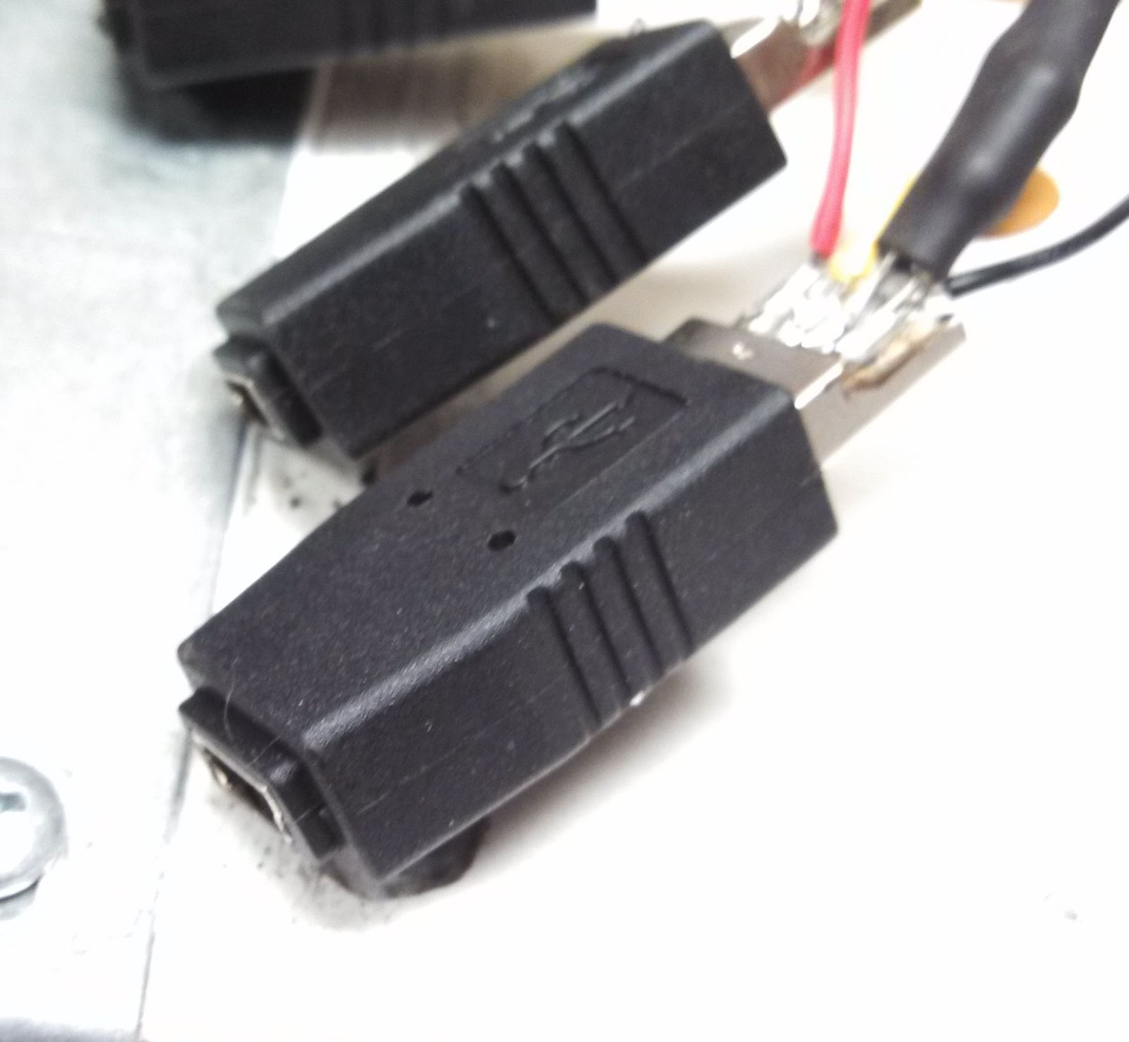
The iGaging scales connect to the remote readouts via mini B USB connectors. I couldn't for the life of me find a cable with a female mini B USB connection on it, so I settled for adapters instead. I opened up the end opposite from the mini USB and soldered my leads directly to the pins. Once everything was soldered and tested I covered all the connections with epoxy.


Mini B USB adapters.

Adapters wired to the Arduino.


I used a 3.5mm stereo headphone jack for the tachometer interface. If I get around to repackaging the Arduino I'll change it to another interface since the 3.5mm jack will short power to ground as the connector is inserted or removed, so you need to power down the Arduino before doing so. It's not a show stopper, but it is annoying. I've hot glued the connector so it can't accidentally pull out while in use. A 10K pull down resistor needed to be added to the tach sensor input.

I bought a small project box from Radio Shack, and aside from the very annoying issue with the Leonardo, the hardest part was installing everything inside the box. I machined slots in for the USB adapters to stick out through. I wedged them in there and glued them in place with epoxy. I also cut a hole for the USB cable which will provide power. To mount the Arduino I secured a thin piece of wood in the bottom of the project box, which the Arduino screwed to.

All packaged up.


I then used Sugru to make the USB connectors look pretty, enclose the USB power cable, and provide it with strain relief. If you haven't used it before, Sugru is a really useful thing to have in your tool box. It comes in little packets and it's silicone rubber which sticks to most things and is moldable for 30 minutes after opening, and cures in 24-48 hours.

Sugru.


The project box with Sugru added.

After that the USB cable was hot glued into the USB jack on the Arduino, the unit was tested again, and then the top was screwed in place. Magnets were glued to the box and the box mounted on the back of the column. It draws its power form a Motorola cell phone charge.

All packed up and ready to go.


There were issues with TouchDRO reading 20-40 times too low on the tachometer. After some time spent on the TouchDRO Google+ development forum I changed the Arduino sketch to one being developed by Ryszhard (http://www.rysium.com/rysium.docs/) and the tach immediately started working. I checked its readings against my laser tachometer and they match to within 20 RPM.

For my readout I'm using a 10" non-widescreen tablet, as I find the non-widescreen format works better for a DRO. This has been one of the best upgrades I could have possibly done and made the mill so much easier and nicer to use. I cannot recommend it enough, and I would never go back to not having one.

Mill: X Axis DRO Cover

Please read the complete article:
http://benchtopmachineshop.blogspot.com/2017/04/mill-touchdro.html


I'm using the iGaging linear scales for my DRO, and noticed my X axis would sometimes jump wildly before going back to normal. It turns out I'd gotten some tiny swarf inside the scale's body. After carefully cleaning it out, I used a 2" aluminum angle completely cover the scale. I needed to cut one side shorter so it would fit on top of the existing cover.

DRO cover in place on X axis.

Wednesday, August 9, 2017

Lathe: TouchDRO

I've wanted a DRO on my lathe for a while to deal with the back lash and confusing dial markings. TouchDRO is the best way to go (for many reasons), but first I needed to attach digital scales to the carriage and cross slide.


When I do threading on the lathe I'll just back out my bit and run the lathe in reverse to rest the carriage, so I have no need for a threading dial and had removed it a while ago. That left a great threaded hole to mount the scale bracket to. I suppose if you still have the threading deal there you could always just sandwich the bracket between the apron and dial. The bracket was easily made from 1/8" 1" aluminum angle. It's a bit overkill and I'll probably trim it down a little more later, but it's not really in the way as is.The screws holding the read head in place use crazy glue as a thread locker, since Loctite will attack plastics.

The design I ended up with places the scale below the lead screw, so it's fairly well protected from swarf. The mounting for it is quite stiff, so I only have the scale attached at one end. That was particularly helpful since I didn't want to try drilling into the lathe' body at the head since it houses the motor right there.The end of the scale was wrapped in electrical tape to electrically isolate the scale from the lathe.

Carriage scale in place with stock readout connected.
Carriage travel at the extreme right of the bed is limited slightly.
 The cross slide digital scale sits to the right of the cross slide. The read head is screwed directly to the carriage and the scale's bracket is connected  slide itself. The bracket was made from a non-conducting composite to electrically isolate the scale. The read head needed 1.5mm machined off the cover's mating surface to lower below the height of the cross slide. The read head is secured by two screws to insure it can't rotate.

New iGaging scale mounted to cross slide

The tachometer, like the mill's, uses a Hall effect sensor since they're much easier to set up than an optical sensor and are just as accurate in this application. The lathe previously had a spindle extension installed, and for the tach's magnet I drilled a hole on the extension and used JB Weld to mount a small neodymium magnet in it. 
Spindle extension with magnet mounted.
 The tach's sensor was mounted to the outside of the lathe's gear cover. I considered mounting on the inside but space would have been an issue and it works perfectly well on the outside. I covered the top of the sensor with epoxy putty to protect it and keep any swarf from shorting it. If you look closely you can see I've bent the sensor itself up and away from the spindle to provide a better orientation to the magnet. The sensor's USB cable is run down the back of the lathe to the Arduino's case.
Hall effect sensor mounted on gear cover.

Unlike the mill's Arduino, I constructed this one using a prototype board. It's much cleaner and easier and I highly recommend it, even though it added $8 to the build. I used standard USB A connectors for the scales' interface since both connectors and cables are much easier to find. This forced me to change the cables on both scales, but that didn't cost much. The tachometer's plug is also USB to avoid the issue I had using a 3.5mm headphone jack for the tach on the mill. Everything was mounted in an old Dell laptop power supply brick's case I had on hand. Neodymium magnets were glued to the case's top for mounting on the back of the lathe.

I'm using a Motorola RAZR phone as the Android device running the TouchDRO application. Since the lathe only has four readouts (X,Z, diameter, and tach) the phone is adequate. It's currently mounted with magnets to the top of the headstock using a bracket I fabricated.
All done.
Like with the mill, setting up a TouchDRO system has made the lathe a lot easier and nicer to use, and I would hate to ever be without it.

Friday, May 26, 2017

Rolle's Dad's Method

Rolle's Dad's Method (RDM) is a brilliant way to accurately measure the alignment of a spindle to the bed/column, and is extremely useful for aligning the head on the mini mill (with the column removed from the base) and the headstock on the mini lathe. It's great because it takes run-out completely out of the equation and only measures the alignment. However, I haven't found a description which I felt practically explained the method to me, and therefore it took me a little while to figure out what it meant. Here's how I do it:

1. Chuck as straight and smooth of a rod in the spindle as you can. Using RDM the smoothness and straightness of the rod doesn't actually matter, but it does make doing the measurements easier.
2. On a lathe mount a DTI on the carriage so it can indicate the rod. On a mini mill I'll move the head to the bottom of the column and then mount the DTI on the column right below the head so it can indicate the rod. You check the X and Y alignment separately, determined by whether you're indicating the side or the top of the rod.
3. You want to indicate two parts of the rod as far apart as possible. On the lathe this means indicating it with the carriage at the chuck, and then as far to the tailstock as possible. On the mini mill it means indicating with the head all the way down and then all the way up. Generally I can get about 7-8" of separation. I'll mark the two points with a Sharpie so I can easily hit the same spots.
4. With the DTI at the head, I turn the spindle by hand and observe the DTI dial, and adjust the dial so the needle is traveling the exact same amount above and below zero; I call this "average zero".
5. Then, without touching the dial, I go to the opposite end of the rod. With the lathe this means moving carriage and with the mini mill the head.
6. Again, I turn the spindle by hand and observe the DTI. The needle will usually move a lot more, but that's ok. I mentally determine where the new average zero would be. The difference between the old average zero and your new average zero is how far out of the alignment you are. Again, it doesn't matter how much the needle moves, all the matters is where your average zeros are.

For example, I'm going to check the horizontal headstock alignment on my mini lathe. I chuck the rod and mount my DTI so it's indicating the side of the rod and move the carriage with the DTI on it all the way to the chuck. I turn the spindle and see the needle is moving a total of .004", and I turn the dial until the needle is traveling exactly 0.002" above zero and 0.002" below zero. I now have my average zero.

Average zero set at the headstock. You can see the Sharpie on the rod marking where I measured.
Without touching the indicator, I move the carriage to the end of the bed. I again turn the spindle by hand and observe the DTI. It's now traveling 0.004" below zero and 0.008" above zero. Mentally I calculate the new average zero is +0.002" on the dial. That means the headstock is 0.002" out of alignment with the bed. If the needle had actually traveled 0.006" below zero and 0.006" above zero it would have meant my headstock was perfectly aligned with the bed.

The needle at average zero at the far end of the bed.
It's reading +0.002", so my headstock is 0.002" out of alignment with the bed. 
Remember, the key is the difference between your average zeroes.