The gibs on the carriage went out of adjustment again, bringing the project I was working on to a temporary end. Highly annoying. Instead of just adjusting them, I took the time to shim them.
The mini lathe's carriage gibs are held in place and adjusted by opposing screws. Two of them push the gib away from the carriage, while three of them tighten the gib to the carriage. In theory, by balancing the screws against each other you can adjust the gib/carriage/bed clearance. In reality it's a crappy system. It's hard to adjust, puts a lot of stress on the gib, and bends the two ends of the big toward to the bed, making it even hard to adjust properly.
To switch to shims remove the small locking screws and leave the socket head cap screws. Starting with the back of the carriage, slide a shim between the gib and carriage, tighten down the three screws and see what it does. If the carriage won't move it's too tight, if there is any movement it's too loose. On mine the back gib ended up with a 0.035" shim. Once that's done, repeat on the front. When testing for movement, make sure there is there isn't any play between the carriage and the bed's prism.
Once the shims are in place, apply blue tread locker to the screws, tighten everything down, and lube the ways.
Monday, April 7, 2014

Mill: Mill Column Tuning Device
I jokingly call this my Mill Column Tuning Device, or MCTD.
It's very difficult to get the column exactly perpendicular to the base using just shims. Additionally, temperature can make the column lean more one direction or another. What I did was fabricate a bracket which is bolted to the base using the column's mounting bolts (longer bolts were required), and then connect the bracket with the top of the column using turnbuckles. Both the side and back of the column received a turnbuckle. Now, as I tighten or loosen the turnbuckle, it will push or pull the column slightly to account for any slight misalignment.
The turnbuckles actually bend the column, so the amount of movement becomes greater the closer to the top of the column you get. Therefore you can't use this system to get the column exactly perpendicular to the base at every position on the column. However, once you've done the best you can with shims, this will let you get it a little closer still, and I'm happy with an incremental improvement.
The rod ends were stock items purchased from McMaster. The turnbuckles themselves were created from 1/2" mild steel rod. The ended were turned down and then threaded on my mini lathe. One end is right hand thread, the other is left hand thread. A M14 nut was slide down the turnbuckle and then welded in place, giving a convenient way to turn them.
The power box was spaced away from the column using simple standoffs to make room for the turnbuckle.
As an added bonus, the bracket was is an ideal location to put my mill's DRO's control box and let me clean up the wires.
UPDATE: I ended up taking it back off the mill. In practice it proved pretty hard to use, and my column is already close to perfect that it just didn't make sense to keep it. Removed it also allowed me to move the spindle light and power feed control back to the top left of the column.
It's very difficult to get the column exactly perpendicular to the base using just shims. Additionally, temperature can make the column lean more one direction or another. What I did was fabricate a bracket which is bolted to the base using the column's mounting bolts (longer bolts were required), and then connect the bracket with the top of the column using turnbuckles. Both the side and back of the column received a turnbuckle. Now, as I tighten or loosen the turnbuckle, it will push or pull the column slightly to account for any slight misalignment.
The turnbuckles actually bend the column, so the amount of movement becomes greater the closer to the top of the column you get. Therefore you can't use this system to get the column exactly perpendicular to the base at every position on the column. However, once you've done the best you can with shims, this will let you get it a little closer still, and I'm happy with an incremental improvement.
The rod ends were stock items purchased from McMaster. The turnbuckles themselves were created from 1/2" mild steel rod. The ended were turned down and then threaded on my mini lathe. One end is right hand thread, the other is left hand thread. A M14 nut was slide down the turnbuckle and then welded in place, giving a convenient way to turn them.
The power box was spaced away from the column using simple standoffs to make room for the turnbuckle.
As an added bonus, the bracket was is an ideal location to put my mill's DRO's control box and let me clean up the wires.
 |
| The system installed on the mill. |
 |
| The bracket the bottom of the turnbuckles attach to. |
 |
| Top of the turn buckles, and the power box spacers. |
 |
| The DRO control box on the bracket and the wires corralled. |
UPDATE: I ended up taking it back off the mill. In practice it proved pretty hard to use, and my column is already close to perfect that it just didn't make sense to keep it. Removed it also allowed me to move the spindle light and power feed control back to the top left of the column.
Monday, September 16, 2013
Quick Note On Safety
Even a mini mill or mini lathe can seriously hurt or even kill you, but some machine tool safety rules can be a little counter intuitive:
- Never wear gloves. Even though you'll end up with more cuts and splinters, the work or tooling can easy grab a glove and pull your hand and arm into the machine. On a large machine once it's pulled your arm in, it can easily pull the rest of you in as well.
- Never wear long sleeves. Similar reasons as above, as a sleeve can easily get grabbed and pulled in.
- Never wear gloves. Even though you'll end up with more cuts and splinters, the work or tooling can easy grab a glove and pull your hand and arm into the machine. On a large machine once it's pulled your arm in, it can easily pull the rest of you in as well.
- Never wear long sleeves. Similar reasons as above, as a sleeve can easily get grabbed and pulled in.
Friday, June 21, 2013
Mill: Packaging My Android DRO
Please read the complete article:
http://benchtopmachineshop.blogspot.com/2017/04/mill-touchdro.html
I finished packaging the Android DRO. It went into a Radio Shack project box which I machined slots in for the USB adaptors to stick out through. I wedged them in there and glued them in place with two part epoxy. I also cut a hole for the USB cable which will provide power. To mount the Arduino I secured a thin piece of wood in the bottom of the project box, which the Arduino is then screwed to.

I then used Sugru to make the USB connectors look pretty, enclose the USB power cable, and provide it with strain relief.

Thanks to my mom for helping with the Sugru molding. If you haven't used it before, Sugru is a really useful thing to have in your tool box. It comes in little packets and it's silicone rubber which sticks to most things and is moldable for 30 minutes after opening, and cures in 24-48 hours.

http://benchtopmachineshop.blogspot.com/2017/04/mill-touchdro.html
I finished packaging the Android DRO. It went into a Radio Shack project box which I machined slots in for the USB adaptors to stick out through. I wedged them in there and glued them in place with two part epoxy. I also cut a hole for the USB cable which will provide power. To mount the Arduino I secured a thin piece of wood in the bottom of the project box, which the Arduino is then screwed to.

I then used Sugru to make the USB connectors look pretty, enclose the USB power cable, and provide it with strain relief.

Thanks to my mom for helping with the Sugru molding. If you haven't used it before, Sugru is a really useful thing to have in your tool box. It comes in little packets and it's silicone rubber which sticks to most things and is moldable for 30 minutes after opening, and cures in 24-48 hours.

After that the USB cable was hot glued into the USB jack on the Arduino, the unit was tested again, and then the top was screwed in place. Done! I don't think I'll mount it on the mill itself since it doesn't really need to be. Oooooooor I may mount it.
 | |||||||
| All packed up and ready to go. |
Monday, June 17, 2013
Mill: Android DRO
Please read the complete article:
http://benchtopmachineshop.blogspot.com/2017/04/mill-touchdro.html
First off, all credit to Yuriy Krushelnytskiy of http://www.yuriystoys.com/.
While poking around the internet for information on the X2 mill, I stumbled on Yuriy's blog. What really intrigued me was his DRO application for the Android: http://www.yuriystoys.com/search/label/DIY%20DRO%20Project
He was using iGaging digital scales, which most X2 owners end up using when installing DROs, connected to an Arduino, which interfaced with an Android via Bluetooth. The DRO app he wrote took the input from the digital scales and displayed it in a nice interface. Just that alone had my attention since the included iGaging remote LCD displays were a little hard to see. However, since all the work is being done in software, it'll be easy to add new features to the DRO in the future. Additionally, since it's open source, you can always add a must have feature yourself. Now that Androids have gotten cheap enough and powerful enough, it makes a lot of sense to do in software what traditional DROs did in hardware. Doing it in software is just much cheaper and much more flexible.
The app is already available in Google Play Store.
Since I had my old HTC Incredible 2 Android phone sitting around I decided to use that instead of a tablet. However, Android DRO needs at least Android v.3 to run, so I needed to root the phone and load a newer Android version. Additionally, once you have Android DRO loaded, if you're using a 4" screen or smaller you'll lose the buttons on the right. To fix this the app needs to be recompiled using Eclipse, which is included in the free Android SDK. You'll need to download the source code and import the project into Eclipse, fix the broken link in the build path, add "Android 4.2.2" and "Android Private Libraries" to your build path, and then drill down to res>values>dimens.xml and change font_lcd from 100dp to 85dp. Then go to "Android Tools" and save it as a signed APK. Go through the wizard, and then use ADB to install the APK file.
I also wanted to reduce the digits displayed. Currently the app shows 0.0001" and 0.001mm, which is greater than the resolution of my iGaging scales, therefore it just clutters the screen with unusable information. Plus, good luck getting 0.0001" precision out of a mini mill. To change it I went to res>values>strings.xml and changed inch_mask to "88.888", inch_format to "00.000", mm_mask to "888.88", and mm_format to "000.00". Since I removed a digit, I was able to cheat the font bigger again, and set font_lcd to 95dp. I again saved it as a signed APK and installed it on the phone.
For the Arduino I bought the Leonardo model which comes without headers, since I like soldered connections. HOWEVER, I learned the hard way the app does NOT like the Leonardo. The app would connect, and then immediately lose connection. Once I switched from the Leonardo to the Uno R3 everything started working beautifully. The Uno R3 comes with headers, so I needed to cut them off and de-solder the pins so I could solder the leads in place.
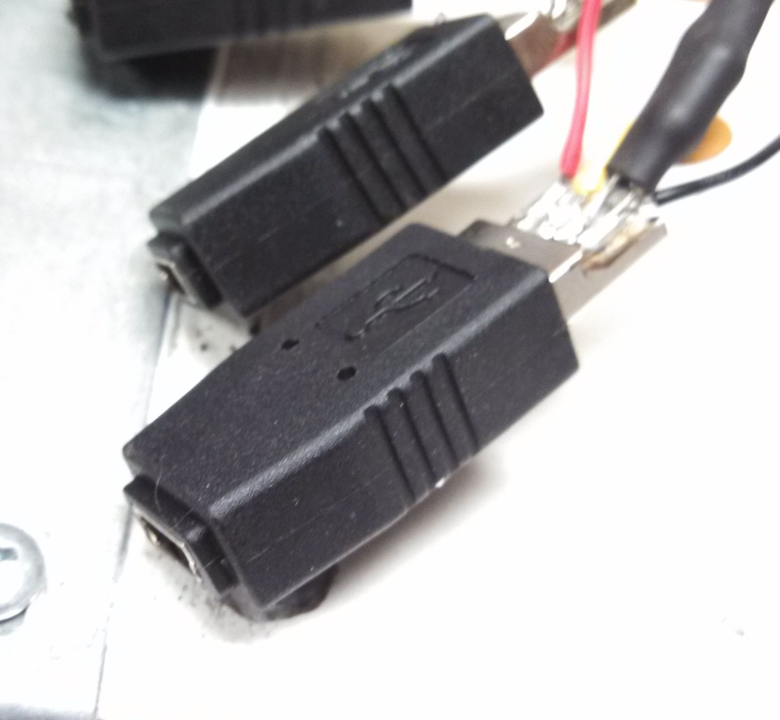
The iGaging scales connect to the remote readouts via mini B USB connectors. I couldn't for the life of me find a cable with a female mini B USB connection on it, so I settled for adaptors instead. I opened up the end opposite from the mini USB and soldered my leads directly to the pins. Once everything was soldered and tested I covered all the connections with epoxy.


I bought a small project box from Radio Shack, and aside from the very annoying issue with the Leonardo, the hardest part was installing everything inside the box.
http://benchtopmachineshop.blogspot.com/2017/04/mill-touchdro.html
First off, all credit to Yuriy Krushelnytskiy of http://www.yuriystoys.com/.
While poking around the internet for information on the X2 mill, I stumbled on Yuriy's blog. What really intrigued me was his DRO application for the Android: http://www.yuriystoys.com/search/label/DIY%20DRO%20Project
He was using iGaging digital scales, which most X2 owners end up using when installing DROs, connected to an Arduino, which interfaced with an Android via Bluetooth. The DRO app he wrote took the input from the digital scales and displayed it in a nice interface. Just that alone had my attention since the included iGaging remote LCD displays were a little hard to see. However, since all the work is being done in software, it'll be easy to add new features to the DRO in the future. Additionally, since it's open source, you can always add a must have feature yourself. Now that Androids have gotten cheap enough and powerful enough, it makes a lot of sense to do in software what traditional DROs did in hardware. Doing it in software is just much cheaper and much more flexible.
The app is already available in Google Play Store.
Since I had my old HTC Incredible 2 Android phone sitting around I decided to use that instead of a tablet. However, Android DRO needs at least Android v.3 to run, so I needed to root the phone and load a newer Android version. Additionally, once you have Android DRO loaded, if you're using a 4" screen or smaller you'll lose the buttons on the right. To fix this the app needs to be recompiled using Eclipse, which is included in the free Android SDK. You'll need to download the source code and import the project into Eclipse, fix the broken link in the build path, add "Android 4.2.2" and "Android Private Libraries" to your build path, and then drill down to res>values>dimens.xml and change font_lcd from 100dp to 85dp. Then go to "Android Tools" and save it as a signed APK. Go through the wizard, and then use ADB to install the APK file.
I also wanted to reduce the digits displayed. Currently the app shows 0.0001" and 0.001mm, which is greater than the resolution of my iGaging scales, therefore it just clutters the screen with unusable information. Plus, good luck getting 0.0001" precision out of a mini mill. To change it I went to res>values>strings.xml and changed inch_mask to "88.888", inch_format to "00.000", mm_mask to "888.88", and mm_format to "000.00". Since I removed a digit, I was able to cheat the font bigger again, and set font_lcd to 95dp. I again saved it as a signed APK and installed it on the phone.
For the Arduino I bought the Leonardo model which comes without headers, since I like soldered connections. HOWEVER, I learned the hard way the app does NOT like the Leonardo. The app would connect, and then immediately lose connection. Once I switched from the Leonardo to the Uno R3 everything started working beautifully. The Uno R3 comes with headers, so I needed to cut them off and de-solder the pins so I could solder the leads in place.
 |
| Uno R3 with the headers and pins removed. |

Demo moving the X and Y axis
Thursday, June 13, 2013
Mill: Bench Top Precision Belt Kit
I decided to preemptively upgrade my mill to belt drive. This way I never have to deal with broken gears, and the mill runs quieter as well. Since I frequently work later at night that's a nice benefit. After researching kits for a while, I found the one made by Bench Top Precision:
http://www.benchtopprecision.com/x2_belt_drive_kit.html
It looked identical to the Little Machine Shop kit, but was significantly cheaper (prices have gone up since I bought it) so I went with it. The seller was great to work with, and the money I saved allowed me to buy additional tooling. After receiving it I see there are a couple notable difference between it and the one from LMS:
Installation was easy, and took less than 30 minutes. Please note you want to install the motor standoffs on the base plate before installing the base plate on the mill. One annoying note is the kit was a mix of metric and Imperial allen bolts, especially since the mill is all metric.

http://www.benchtopprecision.com/x2_belt_drive_kit.html
It looked identical to the Little Machine Shop kit, but was significantly cheaper (prices have gone up since I bought it) so I went with it. The seller was great to work with, and the money I saved allowed me to buy additional tooling. After receiving it I see there are a couple notable difference between it and the one from LMS:
- The LMS kit pulleys use the the stock shaft keys while the BTP kit uses dual set screws, one of which seats in the key way of the shaft.
- The LMS kit has you re-tighten the spindle nut's set screw. On the BTP kit it's inaccessible so instead you use Loctite on the threads.
- The LMS motor pulley is seated down all the way on the motor's shaft, while on the BTP kit the motor pulley is visually aligned with the spindle pulley and then tightened.
Installation was easy, and took less than 30 minutes. Please note you want to install the motor standoffs on the base plate before installing the base plate on the mill. One annoying note is the kit was a mix of metric and Imperial allen bolts, especially since the mill is all metric.

Monday, June 10, 2013
Mill: Labels
I put labels on the mill's hand wheels indicating which direction the table moves. This helps prevent me from accidentally turning the wheel in the wrong direction at the end of a cut.


Subscribe to:
Posts (Atom)