Saturday, December 17, 2022
Nozzle Torque
An E3D V6 style nozzle should be torqued to 3NM or 26.5 in/lbs. Recently E3D has revised it to only 2NM in their support documentation, but it was 3NM for years and 2NM is just too low and risks filament leaks.

Wednesday, August 21, 2019
Printer: ABL Assisted Bed Leveling
ABL still needs a fairly level bed for it to do its thing. I've found if your bed is within 0.2mm of level, then ABL will work great. Fortunately, once you have ABL installed, you can use it to help level your bed. Using the ABL is fast, easy, accurate, and you let the printer do most of the work.
After you open a terminal to the printer using Octoprint, Pronterface, etc., send a G28 to auto home the printer, then add a G29 to do an ABL pass. Once the pass is complete, the ABL's matrix of measurements in millimeters will be displayed in the terminal window. The top left number is the front left corner, and the top right number is the front right corner.

On the Ender 3 the bed leveling M5 screws have a 0.8mm pitch, so each full revolution of a leveling wheel will move the corner 0.8mm. Once you've adjusted the wheels, send another G29 to the printer to do another ABL pass, and keep adjusting as necessary. It's usually taken me three passes to get all my corners within 0.2mm of level.
After you open a terminal to the printer using Octoprint, Pronterface, etc., send a G28 to auto home the printer, then add a G29 to do an ABL pass. Once the pass is complete, the ABL's matrix of measurements in millimeters will be displayed in the terminal window. The top left number is the front left corner, and the top right number is the front right corner.

On the Ender 3 the bed leveling M5 screws have a 0.8mm pitch, so each full revolution of a leveling wheel will move the corner 0.8mm. Once you've adjusted the wheels, send another G29 to the printer to do another ABL pass, and keep adjusting as necessary. It's usually taken me three passes to get all my corners within 0.2mm of level.
Wednesday, April 10, 2019
Mill: Speed Control
NOTE: If you're not comfortable working with electrical component and AC power, then do NOT attempt this modification. Touching the wrong thing can potentially kill you.
My mill is a Grizzly G8689 with the standard brushed motor. All its wires are numbered, I assume for ease of assembly, so I'll refer to the wires by their numbers. I assume the wiring is the same for all brushed motor mills, but your mileage may vary.
The X2 mill's DC motor speed controller is the weak link and not the motor itself. Short of doing a treadmill motor/controller upgrade, you can upgrade just the speed controller and see good gains in both torque and speed. Although the stock controller is a PWM unit, it's not a very good one and is quite limited. It's also a much easier and potentially cheaper upgrade than a treadmill motor.
The common DC controller you'll see in searches if the KBLC-19PM which is just a custom version of the KBIC-120 rated for 125VDC out instead of the standard 90VDC. The KBIC-120 is only rated up to 0.5 HP without a heatsink and the X2's motor is actually 0.5 HP or less, regardless of what the sticker on it says. so you can safely use the KBLC-19PM or the KBIC-120 using the 0.5 HP resistor (0.25 ohm, PN#9841). You can also use the KBMM series of controllers, but the cheaper KBIC works fine. Since I was able to get the best deal on it, I went with the KBIC-125B, which is a KBIC-125 uprated from 90VDC to 125VDC. Aside from the KBIC itself, I also needed a 5k potentiometer. Forunately my KBIC come with a motor fuse, otherwise I would have needed to add one (the mill should use a 7.5A fuse).
The stock controller is screwed to the back of the mill's electrical box, with a small accessory board next to it. The accessory board converts AC to 20VDC to power the fan. To remove the controller loosen all the terminal screws, remove the wires, remove the four screws and remove the board. To make room for the KBIC I also removed the accessory board, turned it, and mounted it to the side of the box using a couple newly drilled holes, some plastic washer, and a pair of pop rivets.
To mount the KBIC I reused one of the vent holes on the side of the box, then measured and drilled a second hole, and using two screws and nuts secured the KBIC's side to the side of the box.
Inside the small controller box I disconnected the motor leads from the switch and connected them to wires 1 and 2 running back to the electrical box. The 5k potentiometer was wiring in using the old potentiometer's wires with a direct swap over. The old potentiometer also incorporates a switch with three wires going to it (AC neutral), I took those three wires and soldered them all together and heat shrinked them.
Back in the electrical box I soldered spade connectors onto the wires to make installation and troubleshooting easier. I then wired it up per this diagram:

On the 20VDC accessory board I connected wire #3 to the AC neutral terminal and connected #4 wire with a short jumper to the AC hot terminal. I removed the yellow LED which was wired in series with the accessory board since it was disrupting its operation. Now the fan runs whenever there's power. I don't think the added cooling is needed, but I didn't see a reason not to.
My mill is a Grizzly G8689 with the standard brushed motor. All its wires are numbered, I assume for ease of assembly, so I'll refer to the wires by their numbers. I assume the wiring is the same for all brushed motor mills, but your mileage may vary.
 |
| The stock controller. You can see the numbered tags on the wires and the terminals. |
The X2 mill's DC motor speed controller is the weak link and not the motor itself. Short of doing a treadmill motor/controller upgrade, you can upgrade just the speed controller and see good gains in both torque and speed. Although the stock controller is a PWM unit, it's not a very good one and is quite limited. It's also a much easier and potentially cheaper upgrade than a treadmill motor.
The common DC controller you'll see in searches if the KBLC-19PM which is just a custom version of the KBIC-120 rated for 125VDC out instead of the standard 90VDC. The KBIC-120 is only rated up to 0.5 HP without a heatsink and the X2's motor is actually 0.5 HP or less, regardless of what the sticker on it says. so you can safely use the KBLC-19PM or the KBIC-120 using the 0.5 HP resistor (0.25 ohm, PN#9841). You can also use the KBMM series of controllers, but the cheaper KBIC works fine. Since I was able to get the best deal on it, I went with the KBIC-125B, which is a KBIC-125 uprated from 90VDC to 125VDC. Aside from the KBIC itself, I also needed a 5k potentiometer. Forunately my KBIC come with a motor fuse, otherwise I would have needed to add one (the mill should use a 7.5A fuse).
 |
| KBIC-125 |
The stock controller is screwed to the back of the mill's electrical box, with a small accessory board next to it. The accessory board converts AC to 20VDC to power the fan. To remove the controller loosen all the terminal screws, remove the wires, remove the four screws and remove the board. To make room for the KBIC I also removed the accessory board, turned it, and mounted it to the side of the box using a couple newly drilled holes, some plastic washer, and a pair of pop rivets.
To mount the KBIC I reused one of the vent holes on the side of the box, then measured and drilled a second hole, and using two screws and nuts secured the KBIC's side to the side of the box.
 |
| KBIC mounted in box with accessory board mounted on the side. In this picture it's already been wired. |
Inside the small controller box I disconnected the motor leads from the switch and connected them to wires 1 and 2 running back to the electrical box. The 5k potentiometer was wiring in using the old potentiometer's wires with a direct swap over. The old potentiometer also incorporates a switch with three wires going to it (AC neutral), I took those three wires and soldered them all together and heat shrinked them.
 |
| The three wires on the old potentiometer which I wired together. |
Back in the electrical box I soldered spade connectors onto the wires to make installation and troubleshooting easier. I then wired it up per this diagram:

On the 20VDC accessory board I connected wire #3 to the AC neutral terminal and connected #4 wire with a short jumper to the AC hot terminal. I removed the yellow LED which was wired in series with the accessory board since it was disrupting its operation. Now the fan runs whenever there's power. I don't think the added cooling is needed, but I didn't see a reason not to.
The emergency cutoff switch is still used and turns AC on and off before it connects to any switch or board. The AC fuse in the diagram isn't used as the mill's existing fuse is used instead.
The "Inhibit" function on the KDIC allows the motor to be turned off electronically. I decided to take advantage of it, as it allows me to set a RPM, and then use the switch to turn the motor on and off without having to reset the speed every time like on the stock controller (note: the switch's direction is now reversed so you might want to relabel it). The KBIC also gave me much finer control over the motor, which was a pleasant surprise. The stock board was frustrating to try and adjust, since the adjustments frequently overlapped. However, on the KBIC they're all nicely separated and discrete.
Once the KBIC is connected, I needed to adjust it for my motor specifically. The first thing I did was adjust Max Speed so the output was 110VDC at full speed. I then adjust the Min Speed so the motor stopped just before the speed knob hit zero. The factory Accel setting was good, but could be adjusted if the motor either spun up to speed too fast or too slow. I left the Current Limit at it's factory value of 1.5x the HP resistor. I also left the IR Compensation as is, but might look at it later if I find the motor RPMs dropping under heavier load; it allows the KBIC to compensate (to a degree) for load to keep the RPMs steady.
However, a couple weeks after upgrading to the KBIC I again upgraded to a KBWS which uses PWM to control the DC voltage.There are two commonly used ways to power a DC motor from AC voltage: SCR and PWM.In short, an SCR will essentially chop off half the AC input and feed that to the motor, with the speed being controlled by where in the AC waveform it starts to feed it to the motor. When the motor is set to full speed this is fine, but at anything less than full speed the motor won't be getting the full voltage. While with PWM the AC is rectified to DC, and then the DC is very rapidly switched on and off to control the speed, so the motor sees rapid, brief inputs of full voltage.
The KB PWM control I use produces a peak voltage of 160VDC which is very rapidly switched on and off to produce a lower average voltage. I was worried about the 110VDC motor being hit with 160VDC, but after research I found if the frequency is high enough, then it doesn't really matter (assuming the peak voltage isn't absurdly high). In fact, a high frequency PWM drive will actually allow the motor to run cooler while producing more torque.
A
quite note, KB Electronics makes a cheaper version of the KBWS called
the KBWD. However, while the KBWD will work, it doesn't have an
electronic stop like the KBWS has. On a mill/lathe the electronic stop
is very handy, since you can set a speed and then use it to turn the
motor one and off without disturbing the speed setting. That feature is
useful enough to me to specifically seek out the more expensive KBWS.
Once the KBIC is connected, I needed to adjust it for my motor specifically. The first thing I did was adjust Max Speed so the output was 110VDC at full speed. I then adjust the Min Speed so the motor stopped just before the speed knob hit zero. The factory Accel setting was good, but could be adjusted if the motor either spun up to speed too fast or too slow. I left the Current Limit at it's factory value of 1.5x the HP resistor. I also left the IR Compensation as is, but might look at it later if I find the motor RPMs dropping under heavier load; it allows the KBIC to compensate (to a degree) for load to keep the RPMs steady.
However, a couple weeks after upgrading to the KBIC I again upgraded to a KBWS which uses PWM to control the DC voltage.There are two commonly used ways to power a DC motor from AC voltage: SCR and PWM.In short, an SCR will essentially chop off half the AC input and feed that to the motor, with the speed being controlled by where in the AC waveform it starts to feed it to the motor. When the motor is set to full speed this is fine, but at anything less than full speed the motor won't be getting the full voltage. While with PWM the AC is rectified to DC, and then the DC is very rapidly switched on and off to control the speed, so the motor sees rapid, brief inputs of full voltage.
The KB PWM control I use produces a peak voltage of 160VDC which is very rapidly switched on and off to produce a lower average voltage. I was worried about the 110VDC motor being hit with 160VDC, but after research I found if the frequency is high enough, then it doesn't really matter (assuming the peak voltage isn't absurdly high). In fact, a high frequency PWM drive will actually allow the motor to run cooler while producing more torque.
In real life this means SCR controllers are cheaper, more robust, and able to handle more current, but are louder (they produce an AC buzz), the motor runs hotter, and the brushes and commutator have a reduced lifespan. PWM controllers are more expensive, have lower current limits, are somewhat easier to break, but they run very silently and the motor runs cooler with a longer brush and commutator life.
Since both the KBIC and KBWS use the same chassis, it was very simple to swap them out. Please note newer KBWS controls come with a shorter capacitor which doesn't require modification of the control box, while the older KBWS would need modification to accommodate their height.
Since both the KBIC and KBWS use the same chassis, it was very simple to swap them out. Please note newer KBWS controls come with a shorter capacitor which doesn't require modification of the control box, while the older KBWS would need modification to accommodate their height.
 |
| KBWS installed in the mill. |
The quieter operation was immediately noticeable and very
welcome. After an extended run the motor was still cool to the touch,
unlike with the KBIC. Ultimately, I think it was a worthwhile upgrade.
Both
the mini mill and mini lathe mostly use PWM controllers stock. However,
the stock controllers are very limited and prone to die. If my choice
was the stock controller or a KBIC/KBLC I would go with the KBIC/KBLC,
even though they're SCR simply for the significantly greater performance
and adjustability they offer. However, if you can get a KBWS for a good
price, that's a better the way to go.
Mill: Gibs
I think the gibs which come with the mill are fine, except the divots for the set screws are woefully inadequate. Because the set screws aren't pushing against a flat, they tend to rotate the gib, which compromises rigidity and creates uneven wear.


I figured if they had a flat nose to push against a flat surface, they'd work a lot better and wouldn't deform. So it was disassembled and thrown in the lathe where its end was extended and faced flat. Since its end turns on the gib I greased it just before assembly.

I also substituted the mini mill Z-axis gib for the Y-axis gib. It needed to be cut to length, but it sits much better and takes up nearly all the space available.
To adjust the table gibs on my mini mill I move the table to the middle of the X axis and set a dial indicator measuring horizontal play at the end of the table. I then lock Y and loosen all the X set screws. I adjust the two outside set screws until I have about 0.0015"-0.002" of measured play in the table. I then adjust the two inside set screws individually by tightening them just until I feel resistance in the hand wheel, then easing them off just slightly.

To fix this I decided to machine proper flats into the gibs for the set screws to sit on. First I removed all the set screws for the gib, then installed and positioned the gib. I sharpened the end of two M4 set screws in my lathe and first installed one and tightened it down, and then tightened the other one in each hole in turn. This left exact center marks for all the set screws. From measurements it looks like the gib angle is 55*, so I used my Wixey angle gauge to set my angle vise.
Since the gib wanted to rotate when the vise was tightened, I placed a section of 1/2" steel rod in the corner formed by the gib and vise jaw, and then used my table clamp set to push down on the rod, effectively locking the gib in place. I then machined the flats using a 3/16" end mill with a plunge cut. For the lock's flat I used a 1/4" end mill. By the way, that gouge you see is what happens when your vise decides to let go of the work.
Since the gib wanted to rotate when the vise was tightened, I placed a section of 1/2" steel rod in the corner formed by the gib and vise jaw, and then used my table clamp set to push down on the rod, effectively locking the gib in place. I then machined the flats using a 3/16" end mill with a plunge cut. For the lock's flat I used a 1/4" end mill. By the way, that gouge you see is what happens when your vise decides to let go of the work.

The set screws were also upgraded from the stock dog point to cup point. The last couple millimeters of the set screws were turned down so they just fit in the gib pocket. This helped position the gib horizontally and keep it from sliding on the set screws.
I also took the opportunity to lap the gib slightly, but it turned out it was pretty flat to begin with. Once everything was reassembled, the gib has much more contact with the dovetail, and I can tighten the set screws tighter without making it hard to move. It was well worth it in my opinion.
I didn't like how the gib locks looked either. They have a rounded nose which pretty quickly becomes deformed through use.

I figured if they had a flat nose to push against a flat surface, they'd work a lot better and wouldn't deform. So it was disassembled and thrown in the lathe where its end was extended and faced flat. Since its end turns on the gib I greased it just before assembly.

I also substituted the mini mill Z-axis gib for the Y-axis gib. It needed to be cut to length, but it sits much better and takes up nearly all the space available.
For the Y axis I lock the X and loosen on the Y set screws. If you have only two Y set screws then adjust them until you have about 0.0015"-0.002" play in the table. If you have four set screws then adjust the two outside ones until you have about 0.0015"-0.002" play, and then individually adjust the two inside ones same as on the X axis.
Of course, when you're machining be sure all the axis are locked except the one you're moving.
Mill: Spindle Bearings
The mini mill uses deep groove radial bearings. They're not ideal for a mill spindle, but they'll work adequately. There are essentially three options for replacement bearings:
1. Deep Groove Radial Ball Bearings (6206 for MT3 spindle) - These are the same as the stock bearings and come as either sealed or shielded. Shielded actually have a tiny gap between the shield and the inner race, so they don't protect as well, but they also produce less heat and have a higher top speed. Sealed protect the bearing better, but they'll produce noticeably more heat and, once they're installed and preloaded, their top speed will be about the same as the top speed of a belt driven mini mill.

ABEC-3 bearings should be used in the mini mill for the lower runout, though most Japanese bearings, even if they're listed as ABEC-1 will actually be ABEC-3. A lot of replacement bearings you see are C3 tolerance. The C3 indicates they have greater clearance inside the bearings. On the mini mill they should be ok to use since the bearings are preloaded. You can also use CN (normal internal clearance) or C2 (reduced internal clearance).
The downside of deep groove radial ball bearings is they cannot handle a lot of preload, and preload is what produces a stiff spindle. In addition, as you preload them their runout increases.
2. Tapered Roller Bearing (30206 for MT3 spindle) - A popular upgrade are tapered roller bearings (TRBs), with people often using cheap car axle bearings. These bearings are incredibly rigid and allow virtually no deflection. They can take huge loads (much higher than a mini mill is capable of). The problem is those axle bearings have a max runout of 0.001" which is pretty bad. On a mill low runout is especially important, as it effects tool chip load, especially on small diameter tools. You can buy higher TRBs (minimum grade C or P5) but they're not easy to find and can be quite expensive. Additionally, TRBs are very sensitive to preload, and have a very small window of acceptable preload. TRBs are also 1.5mm deeper than the stock bearings, which can require some modifications. There are no sealed versions, so some form of seal needs to be fabricated to keep contamination out and grease in. Considering their mounted vertically in the mini mill, keeping the grease in place can be a challenge. Finally, they cannot spin nearly as fast as ball bearings.
3. Angular Contact Ball Bearings (7206 for MT3 spindle) - Unlike deep groove ball bearings, ACs are able to take both axial and radial loads. However, AC bearings are directional, meaning they can only take axial load in one direction. In fact, there is play between the bearing races until preload is applied. ABEC-3 precision 7206 ACs (roughly equal to TRB class C or P5) are fairly readily and relatively cheaply available. They're also the same dimensions as the stock bearings, which make it a direct swap. ACs are much more tolerant of a wide range of preloads, which makes setting the preload much easier and more forgiving than with TRBs. While ACs are less rigid than TRBs, for a machine as small as a mini mill it shouldn't matter at all.
Because of the vertical bearing orientation in the mini mill, grease retention is an issue, and I also found contamination of the lower bearing is an issue. That's why I ultimately used sealed AC bearings. While they're readily available from an over-seas vendor, those bearings are ABEC-1 which have 0.0005" runout. SKF makes a 7206-BE-2RZP (http://www.skf.com/ph/products/bearings-units-housings/ball-bearings/angular-contact-ball-bearings/single-row-angular-contact-ball-bearings/single-row/index.html?designation=7206%20BE-2RZP) sealed AC bearing which is ABEC-3 and is supposed to have ABEC-5 runout. The one place I could readily find them (and for a good price!) was www.123bearing.com.
I made a press for the bearing so I wouldn't have to remove the mill head. Since both the outer and inner races are a press fit, I needed to make adapters for the press which would push both inner and outer races equally. You never press a bearing through the rolling element or you'll destroy it! The adapters were made using two 3" diameter by 3" long pieces of aluminum rod, and a 2" diameter by 1" long steel rod. The press itself is a 5/8" long piece of threaded rod with a nut red Loctited onto one end.
The aluminum was faced on both sides, and then a 5mm long section was turned down to 60mm . The center was then drilled and bored out to 31mm. This allowed it to slip over the top of the spindle and press evenly on both inside and outside bearing race. It also allowed it to center over the top bore of the spindle head when pressing in the bottom bearing. The bottom adapter was again faced on both sides and the end of the OD turned down to 60mm. The center was drilled and bored out to 43mm, which is wide enough to not touch the inner bearing race. The steel rod was faced on both sides, and had the center drilled and bored out to 16.5mm, wide enough to clear the 5/8" threaded rod.
I then thermal fit the bottom bearing onto the spindle (freeze the spindle overnight and heat the bearing to 180*). Alternatively, it can be pressed into the bearing, but care must be taken to only press on the inner race. Make sure the wide part of the outer race faces the top of the spindle, and the wider part of the inner race faces the bottom of the spindle. Remember that the angular contact bearings have play between the races until preloaded. With the aluminum bottom adapter fitted in place I wanted roughly the midpoint of the play in the bearing to put the spindle's nose flush with the adapter's surface. I kept taking facing cuts on the adapter until I reached that point. So with the play removed one direction the nose sat slightly under the adapter's surface's level and with the play removed the other direction it stood slightly proud.
To press the bottom bearing and spindle into the mill head I put the 5/8" threaded rod through the center of the spindle, put the top adapter in place (the top bearing is installed later), put the bottom adapter in place over the spindle and bearing, placed the steel adapter over the bottom adapter, and ran the nut down on the threaded rod, holding everything together. The steel adapter supports the spindle's nose, which in turn supports the bearing's inner race. Since we adjusted the bottom adapter so the inner race would sit in the middle of its play, we can now press the bearing into place without applying any force to the inner race. I lightly oiled the bearing and the bore and tightened the 5/8" rod until the bearing pulled and seated into it's bore.
I then disassembled the top of the press, lightly oiled the top bearing and bore, and pressed it into place as well. On the top I needed additional clearance for the spindle, so I used a PVC pipe fitting; it worked just fine.
Honestly, the system the X2 uses for preload adjustment isn't all that great or accurate. The absolute first thing I did was face both side of the adjustment nut. From the factory it's pretty far off. This will allow even pressure to be applied to the bearing. Next I took the set screw, cut the point off, and faced it. This would still provide enough holding power to keep the nut from turning, but wouldn't damage the spindle threads. To make adjusting the nut easier, I took a 32mm socket and ground it down until I had four teeth to interface with the nut; it's much easier than using a lock ring wrench.
Adjusting the preload is tricky, since I wanted to get between 100 and 125 pounds of preload. Using a torque wrench I measured how much torque was required to remove the play from the spindle, then I added 20 in/lbs of torque to that, and tightened down the nut. It was roughly 55 in/lbs of torque. Using a DTI attached to the mill head I checked for play in the spindle (if the DTI is on the table then it'll also read flex in the column, of which there is a surprising amount); on the mill you shouldn't see any play with properly preloaded bearings.
I then checked the preload by measuring the breakaway torque, meaning the amount of force required to make the spindle start to turn. This can be fairly easily calculated using a thin feeler gauge, a strong magnet, and an scale. You fix the end of the shim to the spindle using the magnet, measure the diameter of the spindle in inches where it's attached, hook the scale to the shim, wrap the shim around the spindle as far as it'll go, and then pull on the scale and see how much force in pounds is required to start turning the spindle. If you multiply that by the radius you get the breakaway torque in in/lbs. For example, I measure at the lock rings, which have a radius of 0.815". My breakaway force measured at 1.25lbs. Therefore, the breakaway torque was 1.02 in/lbs. For a mini lathe or mini mill using AC bearings, about 1 in/lbs is good, and I'd estimate a range of 0.6-1.5 in/lbs being acceptable.
Since grease can effect the breakaway torque I'll turn the spindle in the opposite direction I'm going to measure and then turn it back just slightly and then measure. I've found this technique creates a "dead spot" in the grease and almost completely eliminates its friction.
Then I ran the mill at high speed for 30 minutes while monitoring the temperature of the mill head right next to the bearing. I used a IR thermometer which I pressed against the side of the mill head right at the bearing. I've checked the temperature at that location versus the temperature right at the bearing's outer race using a thermocouple and there is only a couple degrees difference. If the temperature stays under 60* C then you're fine on preload. On mine the temperature barely even reached 45* C. I then made sure to put a witness mark on the nut so I could tighten it to the exact same point every time.
1. Deep Groove Radial Ball Bearings (6206 for MT3 spindle) - These are the same as the stock bearings and come as either sealed or shielded. Shielded actually have a tiny gap between the shield and the inner race, so they don't protect as well, but they also produce less heat and have a higher top speed. Sealed protect the bearing better, but they'll produce noticeably more heat and, once they're installed and preloaded, their top speed will be about the same as the top speed of a belt driven mini mill.

ABEC-3 bearings should be used in the mini mill for the lower runout, though most Japanese bearings, even if they're listed as ABEC-1 will actually be ABEC-3. A lot of replacement bearings you see are C3 tolerance. The C3 indicates they have greater clearance inside the bearings. On the mini mill they should be ok to use since the bearings are preloaded. You can also use CN (normal internal clearance) or C2 (reduced internal clearance).
The downside of deep groove radial ball bearings is they cannot handle a lot of preload, and preload is what produces a stiff spindle. In addition, as you preload them their runout increases.
2. Tapered Roller Bearing (30206 for MT3 spindle) - A popular upgrade are tapered roller bearings (TRBs), with people often using cheap car axle bearings. These bearings are incredibly rigid and allow virtually no deflection. They can take huge loads (much higher than a mini mill is capable of). The problem is those axle bearings have a max runout of 0.001" which is pretty bad. On a mill low runout is especially important, as it effects tool chip load, especially on small diameter tools. You can buy higher TRBs (minimum grade C or P5) but they're not easy to find and can be quite expensive. Additionally, TRBs are very sensitive to preload, and have a very small window of acceptable preload. TRBs are also 1.5mm deeper than the stock bearings, which can require some modifications. There are no sealed versions, so some form of seal needs to be fabricated to keep contamination out and grease in. Considering their mounted vertically in the mini mill, keeping the grease in place can be a challenge. Finally, they cannot spin nearly as fast as ball bearings.
 |
| Tapered roller bearing cutaway. |
3. Angular Contact Ball Bearings (7206 for MT3 spindle) - Unlike deep groove ball bearings, ACs are able to take both axial and radial loads. However, AC bearings are directional, meaning they can only take axial load in one direction. In fact, there is play between the bearing races until preload is applied. ABEC-3 precision 7206 ACs (roughly equal to TRB class C or P5) are fairly readily and relatively cheaply available. They're also the same dimensions as the stock bearings, which make it a direct swap. ACs are much more tolerant of a wide range of preloads, which makes setting the preload much easier and more forgiving than with TRBs. While ACs are less rigid than TRBs, for a machine as small as a mini mill it shouldn't matter at all.
 |
| Angular contact ball bearing cutaway. |
On a related note, you may have seen instruction for installing ACs on the mini lathe on other sites. The problem with those instructions is they have you pressing in the bearing through the rolling elements. In other words, you're applying pressure to the inside race in order to press the outside race into its bore. You should never do this. The manufacturers will always tell you not to press the bearing through the rolling elements because, while the bearings can handle high dynamic loads, the high static load from pressing can damage both the races and the balls themselves, greatly reducing the life of the bearing.
Before starting, I chucked the spindle in the lathe and sanded the top bearing seat with 400 sandpaper then a Scotch-Brite until the bearing was a light press fit. It's important to accurately set the preload later on, and apply less static force on the bearing while doing so.I made a press for the bearing so I wouldn't have to remove the mill head. Since both the outer and inner races are a press fit, I needed to make adapters for the press which would push both inner and outer races equally. You never press a bearing through the rolling element or you'll destroy it! The adapters were made using two 3" diameter by 3" long pieces of aluminum rod, and a 2" diameter by 1" long steel rod. The press itself is a 5/8" long piece of threaded rod with a nut red Loctited onto one end.
The aluminum was faced on both sides, and then a 5mm long section was turned down to 60mm . The center was then drilled and bored out to 31mm. This allowed it to slip over the top of the spindle and press evenly on both inside and outside bearing race. It also allowed it to center over the top bore of the spindle head when pressing in the bottom bearing. The bottom adapter was again faced on both sides and the end of the OD turned down to 60mm. The center was drilled and bored out to 43mm, which is wide enough to not touch the inner bearing race. The steel rod was faced on both sides, and had the center drilled and bored out to 16.5mm, wide enough to clear the 5/8" threaded rod.
I then thermal fit the bottom bearing onto the spindle (freeze the spindle overnight and heat the bearing to 180*). Alternatively, it can be pressed into the bearing, but care must be taken to only press on the inner race. Make sure the wide part of the outer race faces the top of the spindle, and the wider part of the inner race faces the bottom of the spindle. Remember that the angular contact bearings have play between the races until preloaded. With the aluminum bottom adapter fitted in place I wanted roughly the midpoint of the play in the bearing to put the spindle's nose flush with the adapter's surface. I kept taking facing cuts on the adapter until I reached that point. So with the play removed one direction the nose sat slightly under the adapter's surface's level and with the play removed the other direction it stood slightly proud.
To press the bottom bearing and spindle into the mill head I put the 5/8" threaded rod through the center of the spindle, put the top adapter in place (the top bearing is installed later), put the bottom adapter in place over the spindle and bearing, placed the steel adapter over the bottom adapter, and ran the nut down on the threaded rod, holding everything together. The steel adapter supports the spindle's nose, which in turn supports the bearing's inner race. Since we adjusted the bottom adapter so the inner race would sit in the middle of its play, we can now press the bearing into place without applying any force to the inner race. I lightly oiled the bearing and the bore and tightened the 5/8" rod until the bearing pulled and seated into it's bore.
I then disassembled the top of the press, lightly oiled the top bearing and bore, and pressed it into place as well. On the top I needed additional clearance for the spindle, so I used a PVC pipe fitting; it worked just fine.
 |
| Bearing press assembled using old spindle and bearing. |
Honestly, the system the X2 uses for preload adjustment isn't all that great or accurate. The absolute first thing I did was face both side of the adjustment nut. From the factory it's pretty far off. This will allow even pressure to be applied to the bearing. Next I took the set screw, cut the point off, and faced it. This would still provide enough holding power to keep the nut from turning, but wouldn't damage the spindle threads. To make adjusting the nut easier, I took a 32mm socket and ground it down until I had four teeth to interface with the nut; it's much easier than using a lock ring wrench.
 |
| 32mm socket ground down to fit the spindle nut. Regarding the finish, I did it with an angle grinder, so what do you expect? |
Adjusting the preload is tricky, since I wanted to get between 100 and 125 pounds of preload. Using a torque wrench I measured how much torque was required to remove the play from the spindle, then I added 20 in/lbs of torque to that, and tightened down the nut. It was roughly 55 in/lbs of torque. Using a DTI attached to the mill head I checked for play in the spindle (if the DTI is on the table then it'll also read flex in the column, of which there is a surprising amount); on the mill you shouldn't see any play with properly preloaded bearings.
I then checked the preload by measuring the breakaway torque, meaning the amount of force required to make the spindle start to turn. This can be fairly easily calculated using a thin feeler gauge, a strong magnet, and an scale. You fix the end of the shim to the spindle using the magnet, measure the diameter of the spindle in inches where it's attached, hook the scale to the shim, wrap the shim around the spindle as far as it'll go, and then pull on the scale and see how much force in pounds is required to start turning the spindle. If you multiply that by the radius you get the breakaway torque in in/lbs. For example, I measure at the lock rings, which have a radius of 0.815". My breakaway force measured at 1.25lbs. Therefore, the breakaway torque was 1.02 in/lbs. For a mini lathe or mini mill using AC bearings, about 1 in/lbs is good, and I'd estimate a range of 0.6-1.5 in/lbs being acceptable.
Since grease can effect the breakaway torque I'll turn the spindle in the opposite direction I'm going to measure and then turn it back just slightly and then measure. I've found this technique creates a "dead spot" in the grease and almost completely eliminates its friction.
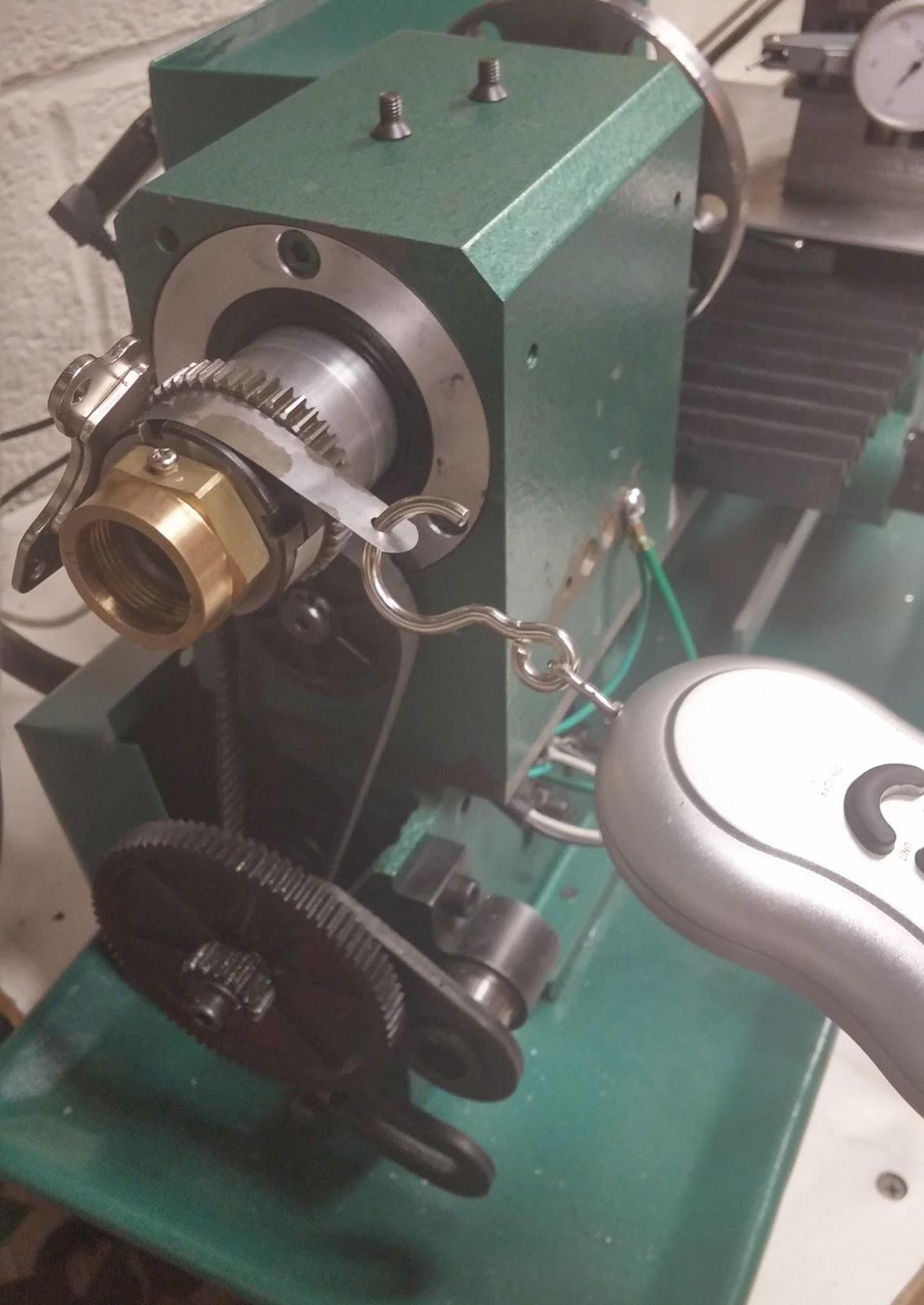 | |||||
| Measuring the breakaway torque on the mini lathe. |
Then I ran the mill at high speed for 30 minutes while monitoring the temperature of the mill head right next to the bearing. I used a IR thermometer which I pressed against the side of the mill head right at the bearing. I've checked the temperature at that location versus the temperature right at the bearing's outer race using a thermocouple and there is only a couple degrees difference. If the temperature stays under 60* C then you're fine on preload. On mine the temperature barely even reached 45* C. I then made sure to put a witness mark on the nut so I could tighten it to the exact same point every time.
Mill: Vises
While prefer clamping directly to the table, I like vises because they're already trammed, so anything I clamp with it I know is already aligned. I primarily use two: a screwless precision vise and an angle drill press vise.
The 3" screwless precision vise fits beautifully on the mini mill and has more than enough clamping power for the machine. Be sure buy one with slots on the sides instead of just holes, since it makes clamping the vise at angles much easier. I purchased mine from Shars and paid about $54 shipped.
As soon as it arrived I made two modifications. I removed the holder the bolt threads into, and removed the cross piece from it which hooks into the grooves on the bottom of the vise. I then turned a new cross piece on the lathe whose length just fits. This keeps the assembly from rotating when tightening or loosening the vise. Second, I put a spring the bolt. This keeps tension on the bolt at all times, making it much easier to move and hook the cross piece.
One of the biggest annoyances using the precision screwless vise was loosening the jaw and accidentally unscrewing it from the T bracket which holds the cross bar that hooks into the base. After having it happen it again in the middle of a project I took the screw which connects the jaw to the T and turned it smooth starting 5 threads from the end.
I then ground a flat on the T right where it threads onto the screw. I then assembled the vise, threaded the screw into the T, and peened the flat to capture the screw. Now, no more accidentally unscrewing it.
As soon as it arrived I made two modifications. I removed the holder the bolt threads into, and removed the cross piece from it which hooks into the grooves on the bottom of the vise. I then turned a new cross piece on the lathe whose length just fits. This keeps the assembly from rotating when tightening or loosening the vise. Second, I put a spring the bolt. This keeps tension on the bolt at all times, making it much easier to move and hook the cross piece.
One of the biggest annoyances using the precision screwless vise was loosening the jaw and accidentally unscrewing it from the T bracket which holds the cross bar that hooks into the base. After having it happen it again in the middle of a project I took the screw which connects the jaw to the T and turned it smooth starting 5 threads from the end.
 |
| Middle section of screw turned smooth. |
I then ground a flat on the T right where it threads onto the screw. I then assembled the vise, threaded the screw into the T, and peened the flat to capture the screw. Now, no more accidentally unscrewing it.
Another reason I like the screwless vise is because I don't need a swivel base to rotate it. I can just loosen the clamps, rotate the vise on the table, check it with my protractor, and tighten the clamps back down. This provides more rigidity and more space between the head and table. Making the clamps is a good project for the mill.
The angle drill press vise isn't a milling vise, and has a whole set of issues because of it. The moving jaw will always want to lift when tightening, so I need to tap it with a hammer once it's tight and also make sure the work didn't move, thought using parallels helps since I can carefully tap the work back down until it's resting fully in the parallels. The vise also isn't super stiff, but for the power the X2 has it's adequate. Finally, it can be a bit of a chore setting the angle on it, and usually requires a bit of tapping it back and forth with a hammer. However, the angle adjustment is dovetailed, hardly has any play, can be locked very solidly, and has basic angles preset with the use of a pin. To set a precise angle I just zero my Wixy digital angle gauge on the table and then stick it on the vise and set my angle. Some operations on the mill would be pretty difficult to set up without an angle vise, so I'm happy to deal with its shortcomings, especially since it only cost me $43 brand new from Sears.
I also ended up getting a 3" Kurt-style milling vise. The Kurt-style vise forces the moving jaw downward as it's tightened, which keeps the part from lifting. While it's not quite as precise as the screwless vise, it's faster to use. It did need a lot of cleanup work. The Casting for the jaw where it meets was the nut was deformed with extra material in the jaw, so I Dremeled away the extra. Also with the Dremel I smoothed out the location where the hemisphere rides in the jaw. After this I lubed it up and reassembled it.
 |
| My preferred vises. |
I also ended up getting a 3" Kurt-style milling vise. The Kurt-style vise forces the moving jaw downward as it's tightened, which keeps the part from lifting. While it's not quite as precise as the screwless vise, it's faster to use. It did need a lot of cleanup work. The Casting for the jaw where it meets was the nut was deformed with extra material in the jaw, so I Dremeled away the extra. Also with the Dremel I smoothed out the location where the hemisphere rides in the jaw. After this I lubed it up and reassembled it.
Ultimately, the precision screwless vise is what I prefer over the Kurt-style vise. It's very easy to set up and square up, it's high capacity is really nice, and with my modifications it's not much slower than the Kurt-style.
Printer: Belt Tension
There is very little good information on what correct belt tension is, and virtually nothing on empirically setting belt tension.
Gates, the creator of the GT2 belt, recommends a tension of 6 to 8 pounds of tension when using a 6mm GT2 belt for registration like in a printer. A NEMA 17 stepper motor can handle 6.7 pounds (30N) of radial force centered at 17mm from the motor's face (something to bear in mind if you're using dampers).
Gates, the creator of the GT2 belt, recommends a tension of 6 to 8 pounds of tension when using a 6mm GT2 belt for registration like in a printer. A NEMA 17 stepper motor can handle 6.7 pounds (30N) of radial force centered at 17mm from the motor's face (something to bear in mind if you're using dampers).
Because the belt wraps around the motor's shaft, the radial force on the stepper is double the belt tension, at the minimum of 6 pounds tension recommended by Gates, there's 12 pounds of radial force on the shaft. However, the allowed radial force increases linearly inversely proportional to the pulley center to motor's face distance. For example, if the pulley is centered at 8.5mm from the motor's face (half of 17mm), then the maximum allowed tension doubles to 13.4 pounds.
NOTE: Moon's bearing life charts indicate the radial limit can go as high as 8 pounds, though with reduced bearing life.
To actually measure the tension the easiest and most precise way is via its vibration frequency. To calculate our target frequency we use Mersenne's equation 22:

Where f is the frequency, L is the length of the belt between contact points in meters, μ is the belt density in kilograms per meter, and F is the tension in Newtons (1 pound equals 4.44822 N). The density of a 6mm GT2 belt is 0.0083 kg/m (both stock and genuine Gates).
Given this, we want a belt tension of 6 pounds with the pulley centered 9.5mm or less from the motor's face. If the pulley center is further out, then the belt must either be tensioned lower or reduced bearing life must be accepted.
NOTE: The Ender 3 pulleys are centered 10mm from the motor's face. In practice I've found tensioning the belts at 6 pounds doesn't appreciably decrease the stepper bearing life
 |
| From the Moons' catalog (see link below). |
 |
| From the Gates catalog (see link below). |
To actually measure the tension the easiest and most precise way is via its vibration frequency. To calculate our target frequency we use Mersenne's equation 22:
Simplified, for 6 pounds force with a GT2 belt, the formula is:
Hertz = 28531 / mm
On the Ender 3 specifically, with the hotend carriage against the limit switch, the belt between the carriage and idler is 0.302 meters (302mm) long, so the target frequency is 94 Hz.
On the Ender 3 specifically, with the hotend carriage against the limit switch, the belt between the carriage and idler is 0.302 meters (302mm) long, so the target frequency is 94 Hz.
NOTE: Previously this number was mistakenly changed to 86 Hz. The correct figure is 94 Hz.
Again on the Ender 3, with the bed pushed all the way back, the exposed belt is 0.253 meters (253mm) long, so the target frequency is 113 Hz.
I found the best way to measure the frequency is the Spectroid app for Android. It produces a waterfall display of the frequency, so it's easy to see what the belt frequency actually is. Pluck the belt like a guitar string and look for the biggest spike. Just tap the waterfall display and it'll give you the frequency selected. The belt will naturally have multiple harmonics, but those will be significantly smaller on the waterfall display and can be ignored. From there just adjust the belt tension until you hit the target frequency.
Again on the Ender 3, with the bed pushed all the way back, the exposed belt is 0.253 meters (253mm) long, so the target frequency is 113 Hz.
I found the best way to measure the frequency is the Spectroid app for Android. It produces a waterfall display of the frequency, so it's easy to see what the belt frequency actually is. Pluck the belt like a guitar string and look for the biggest spike. Just tap the waterfall display and it'll give you the frequency selected. The belt will naturally have multiple harmonics, but those will be significantly smaller on the waterfall display and can be ignored. From there just adjust the belt tension until you hit the target frequency.

Wednesday, March 27, 2019
Printer: Creality Eccentric
The stock Creality extruder side v-slot wheel eccentric is an eccentric only on one side and just a regular spacer on the other. This not only means the wheel move in a cone shape instead of just in/out, it also means the two outside wheels ALSO slightly move in a cone shape. So you end up with the wheels riding slightly cocked to one side in the extrusion.
 |
| Stock setup. |
So I drilled out plate with a 9/32" drill bit and added a second eccentric in place of the spacer. If you don't use a drill press or mill, a step drill bit should do a good job of keeping it centered. I marked the spacers with one divot on the short side and two divots on the long side, so I can easily see which direction they're facing. I now need to manually keep the two eccentrics synced up, but that's not really a problem, and it's much better than stock setup. The adjustment is much more predictable now, and I can get all the play out with the wheels still relatively loose.
 |
| Dual marked eccentrics. |
Monday, March 11, 2019
Printer: Applying PEI Sheet
Almost all PEI sheets use 3M 486MP adhesive (transfer tape) to glue them to the bed. Most methods involve a dry application where you roll the adhesive on while slowly squeezing bubbles out. Regardless of how well you do it, you'll still end up with tiny bubbles. If you get a bigger bubble it will bulge up when the bed is heated. Plus, 486MP is incredibly tenacious stuff, and if you apply it even a little wrong there's no way to recover from it.
The solution is doing a wet install. 3M doesn't officially recommend it, but it works well. You want to mix 1 litter of water with 3 drops of liquid dish soap and put it in a sprayer. Clean the bed well, then liberally spray it down with the water. Peel the back off the 486MP and liberally spray it down with water as well. Then roll it onto the bed, and squeegeeing the water out from under as you go; I usually use a credit card. Then put it between two flat surfaces, put some weight on top, and let it sit for two days.
If the 486MP didn't come pre-applied on the PEI sheet, repeat the previous steps to glue the PEI to the adhesive installed on the bed, and sandwich it again for two days.
The solution is doing a wet install. 3M doesn't officially recommend it, but it works well. You want to mix 1 litter of water with 3 drops of liquid dish soap and put it in a sprayer. Clean the bed well, then liberally spray it down with the water. Peel the back off the 486MP and liberally spray it down with water as well. Then roll it onto the bed, and squeegeeing the water out from under as you go; I usually use a credit card. Then put it between two flat surfaces, put some weight on top, and let it sit for two days.
If the 486MP didn't come pre-applied on the PEI sheet, repeat the previous steps to glue the PEI to the adhesive installed on the bed, and sandwich it again for two days.
Sunday, June 24, 2018
Mill: Handles
I don't like the stock mill handles. They work ok, but vibrate a lot and make noise, and don't feel too good to use. I made some quick replacements using some ABS rod and some cheap flanged bearings I bought on eBay. The fit of the bearings doesn't need to be precise in the ABS since the bolt will hold everything together. The bolt head was turned down and beveled to give it a nicer feel. Medium thread locker was used since there wasn't room for a lock nut anymore.
It works well and there isn't anymore noise. However, the cheap bearings I used feel pretty notchy with any pressure on them, so I might upgrade to better bearings if these wear out.


It works well and there isn't anymore noise. However, the cheap bearings I used feel pretty notchy with any pressure on them, so I might upgrade to better bearings if these wear out.


Tuesday, December 12, 2017
Way Oil
Any oil is better than no oil, but way specific oil works best. The most commonly recommended one is Mobil Vactra 2. However, several years ago the formula was redone with fewer tackifiers to work with synthetic flood coolant. However, this caused big issues for the printing industry, so Mobil created Vacuoline 1409 which used the exact same formula as the old Vactra 2:
http://www.practicalmachinist.com/vb/general-archive/mobile-vactra-2-a-86367-post163414/#post163414
For small, manual machines a tacky oil which stays in place is recommended, so while Vactra 2 works ok, the best option is Vacuoline 1409.
This is a place which sells 16 oz. bottles of Vacuoline 1409 online:
http://www.brwtechnologies.com/Vacuoline_1409_p/mobil_vacuoline_1409.htm
http://www.practicalmachinist.com/vb/general-archive/mobile-vactra-2-a-86367-post163414/#post163414
For small, manual machines a tacky oil which stays in place is recommended, so while Vactra 2 works ok, the best option is Vacuoline 1409.
This is a place which sells 16 oz. bottles of Vacuoline 1409 online:
http://www.brwtechnologies.com/Vacuoline_1409_p/mobil_vacuoline_1409.htm
Wednesday, November 15, 2017
Mill: Screwless Vise Clamps
One of the downside to a screwless vise is having to make clamps to hold it to the table. However, if you have a table clamping kit (which everyone should have), then you can use the smallest clamp with a low profile bolt to clamp the vise in place. This saves some work, but it also distributes the weight well on the table, which keeps any dents or divots from forming.
 |
| Clamp in place and tightened down. |
Mill: Table Stops
The X2 large table has a slot cut in the front for table stops. To make them I took M6 coupling nuts and milled 5mm on the end down to 6mm wide, then I cut 11mm of the couple nut. This gave me an easy little T-nut to use. I then used M6 Allen bolts with a spacer to mount them on the table.
The table's base has two M4 holes to mount the stop. I milled one from 2.5mm aluminum plate and mounted it up.
I now move the table where I want it, move the stop until it touches, and then I can repeat to about 0.001".
 |
| M6 coupling nut, T-nut, and M6 Allen bolt with spacer. |
The table's base has two M4 holes to mount the stop. I milled one from 2.5mm aluminum plate and mounted it up.
I now move the table where I want it, move the stop until it touches, and then I can repeat to about 0.001".
 |
| Stop mounted to table base and movable stop mounted on table. |
Friday, November 10, 2017
Mill: Head Alignment
My first post about my mill regarded aligning the head to the column. Back then I remove the column from the base so the table wouldn't interfere.
Recently I had to realign the head again, and used a much easier technique to do it. First I remove the support spring from the head so I could extend it above the top of the column. Then I chucked a straight and polish rod using my ER25 chuck. You can use pretty much anything to hold it, but it helps if it's low profile. With the rod extended a little over 4" from the chuck face, and the head could move a total of about 6" from the rod touching the table to the head reaching the top of the column.
I clamped my vise vertically to the table and used it to hold a DTI which indicated the rod. I then used Rolle's Dad's Method (RDM) to check the alignment of the rod. In my case the head was 0.0015" over 4" out of alignment.
I then moved the head up past the top of the column until the top two bolts holding the head together were exposed, and loosened them both. I then tightly tapped my motor mount with a rubber mallet to adjust the head. Weirdly, I found tapping it on the right side would rotate the head clockwise. After each adjustment with the hammer I'd check the alignment using RDM. From experience I knew tightening the bolts would rotate the head counter-clockwise about 0.0015" as measured with this setup, so I accounted for that.
Once the alignment was where I wanted it, I again raised the head above the column and in small increments I tightened the two bolts down. You want to get them nice and tight. I think checked the alignment again using RDM. Finally, I carefully lifted up the head until the lower head were just exposed and checked to make sure they were still tight as well, and then checked my alignment once more.
Ultimately, this way was much faster and easier than dismounting the column.
Recently I had to realign the head again, and used a much easier technique to do it. First I remove the support spring from the head so I could extend it above the top of the column. Then I chucked a straight and polish rod using my ER25 chuck. You can use pretty much anything to hold it, but it helps if it's low profile. With the rod extended a little over 4" from the chuck face, and the head could move a total of about 6" from the rod touching the table to the head reaching the top of the column.
I clamped my vise vertically to the table and used it to hold a DTI which indicated the rod. I then used Rolle's Dad's Method (RDM) to check the alignment of the rod. In my case the head was 0.0015" over 4" out of alignment.
 |
| In the middle of checking the head alignment. |
I then moved the head up past the top of the column until the top two bolts holding the head together were exposed, and loosened them both. I then tightly tapped my motor mount with a rubber mallet to adjust the head. Weirdly, I found tapping it on the right side would rotate the head clockwise. After each adjustment with the hammer I'd check the alignment using RDM. From experience I knew tightening the bolts would rotate the head counter-clockwise about 0.0015" as measured with this setup, so I accounted for that.
Once the alignment was where I wanted it, I again raised the head above the column and in small increments I tightened the two bolts down. You want to get them nice and tight. I think checked the alignment again using RDM. Finally, I carefully lifted up the head until the lower head were just exposed and checked to make sure they were still tight as well, and then checked my alignment once more.
Ultimately, this way was much faster and easier than dismounting the column.
Wednesday, November 8, 2017
Mill: Bearing Seal
A surprising amount of shavings make it up to the bottom of the mill head. When I was using open bearings, even with a shield in place they became contaminated. Even though I'm using sealed bearings now, I wanted additional protection. So like on the lathe, I made a new bearing cover for the mill which accepted a standard size oil seal.
For a MT3 spindle you want a 40x55x5 oil seal.Since the bearings are sealed, I didn't need the oil seal's inner lip, so I cut it off to reduce friction. The seal could actually have been pressed into the stock plastic bearing cover, but I figured aluminum would be more durable and prevent potential problems in the future.
If you want to run open bearings on the mill you'd pretty much need to do something like this to retain the grease and exclude contaminants. If you have a R8 spindle and upgrade the bearings, this is almost a mandatory upgrade since I've only seen open 7007 AC bearings.
For a MT3 spindle you want a 40x55x5 oil seal.Since the bearings are sealed, I didn't need the oil seal's inner lip, so I cut it off to reduce friction. The seal could actually have been pressed into the stock plastic bearing cover, but I figured aluminum would be more durable and prevent potential problems in the future.
If you want to run open bearings on the mill you'd pretty much need to do something like this to retain the grease and exclude contaminants. If you have a R8 spindle and upgrade the bearings, this is almost a mandatory upgrade since I've only seen open 7007 AC bearings.
 |
| Bearing cover with oil seal installed on the mill. |
Monday, October 16, 2017
Shims
For shims I use feeler gauges since they're cheap, precise, come in an assortment of sizes, and have the size written on the shim. I usually use this set from Amazon with starts at 0.0015" (0.038mm) :
https://www.amazon.com/dp/B0009OMY9C
If I need larger or thinner shims I'll go with this assortment pack which goes down to 0.001":
https://www.amazon.com/dp/B00065UXD8
Aluminum foil also makes good shim stock with standard aluminum foil being 0.0006" while heavy duty aluminum foil is 0.0008".
I always measure my shims before using them since I've found they're sometimes mislabeled.
There isn't much reason to be worried about galvanic corrosion between aluminum shims and cast iron, and the potential between them is extremely low. Aluminum foil is approximately 0.90V while cast iron is approximately 0.85V. Even harsh environments allow a difference up to 0.15V, with a temperature controlled environment allowing up to 0.5V.
However, I'd recommend against using stainless steel shims, since they have a significantly greater potential of corroding steel or cast iron.
https://www.engineersedge.com/galvanic_capatability.htm
https://www.amazon.com/dp/B0009OMY9C
If I need larger or thinner shims I'll go with this assortment pack which goes down to 0.001":
https://www.amazon.com/dp/B00065UXD8
Aluminum foil also makes good shim stock with standard aluminum foil being 0.0006" while heavy duty aluminum foil is 0.0008".
I always measure my shims before using them since I've found they're sometimes mislabeled.
There isn't much reason to be worried about galvanic corrosion between aluminum shims and cast iron, and the potential between them is extremely low. Aluminum foil is approximately 0.90V while cast iron is approximately 0.85V. Even harsh environments allow a difference up to 0.15V, with a temperature controlled environment allowing up to 0.5V.
However, I'd recommend against using stainless steel shims, since they have a significantly greater potential of corroding steel or cast iron.
https://www.engineersedge.com/galvanic_capatability.htm
Tuesday, September 19, 2017
Mill: TouchDRO
First off, all credit to Yuriy Krushelnytskiy of http://www.yuriystoys.com/.
One of the biggest problems with the X2 is the amount of backlash in all the axis. Instead of trying to lessen the backlash I installed TouchDRO on all three axis. Since they read the table's and head's position directly, you can pretty much ignore the backlash present.
While poking around the internet for information on the X2 mill, I stumbled on Yuriy's blog. What really intrigued me was his DRO application for the Android: http://www.yuriystoys.com/search/label/DIY%20DRO%20Project
He was using iGaging digital scales, which most X2 owners end up using when installing DROs, connected to an Arduino, which interfaced with an Android via Bluetooth. The DRO app he wrote took the input from the digital scales and displayed it in a nice interface. Just that alone had my attention since the included iGaging remote LCD displays were a little hard to see. However, since all the work is being done in software, it'll be easy to add new features to the DRO in the future. Additionally, since it's open source, you can always add a must have feature yourself. Now that Androids have gotten cheap enough and powerful enough, it makes a lot of sense to do in software what traditional DROs did in hardware. Doing it in software is just much cheaper and much more flexible.
If you have the tilting column, the X scale needs to be offset not to lose travel from the read head hitting the column pivot, the aluminum L channel being used as a chip shield makes a pretty convenient offset mount. With the solid column mill the X scale can be mounted centered.
I used a 2" aluminum angle completely cover the scale, cutting down one side so it fits on top of the chip shield. Without it, tiny chips can get inside the read head and cause reading jumps.
 |
| Offset X scale for column pivot clearance. |
 |
| Centered X scale on solid column mill. |
 |
| Chip cover in place over the scale. |
The Y scale in mounted to the base on the left of the mill. The base's sides have a slight angle to them, but that doesn't matter when mounting the scale so long as it remains parallel to Y axis. I've found the table itself shields the scale sufficiently.
 |
| Y scale mounted. |
Once I installed the gas spring and removed the old torsion spring, installing the Z axis DRO was super easy. I removed the ruler on the left side of the column a while ago, since it was so course it was pretty much useless. The 12" iGaging digital scale was the perfect length to screw right into the holes left by the ruler. I then quickly fabricated a bracket to connect the scale's reader to the threaded hole on the head which used to hold the ruler's indicator. Perfect.
 |
| Z scale mounted using existing threaded holes. |
At first I had tried using a prepackaged optical sensor for Arduino (available on Amazon), but switched to a Hall effect magnetic sensor since they're easier to use and for this application tend to be just as accurate. I was able to buy them already mounted on a psb with a LS393 comparator (http://www.amazon.com/dp/B009M86TFG/). The comparator allows you to have an essentially digital signal with it either on or off.
I
already have a belt drive installed, so I drilled two holes at opposite
ends of the top pulley and JB Welded in small neodymium magnets. The
top of the Hall effect sensor psb was covered with epoxy putty to
protect it from swarf. Then it was attached to the pulley cover using
foam tape and a mounting screw. The sensor itself hangs over the back of
the cover and directly over the path of the magnets.
For the Arduino I bought the Leonardo model which comes without headers,
since I like soldered connections. However, I learned the hard way the
app does NOT like the Leonardo. The app would connect, and then
immediately lose connection. Once I switched from the Leonardo to the
Uno R3 everything started working beautifully. The Uno R3 comes with
headers, so I needed to cut them off and de-solder the pins so I could
solder the leads in place. | |
| Magnets on the pulley. The black sections were for the optical sensor. |
 |
| The Hall effect sensor covered with epoxy putty and mounted on the pulley cover. |
 |
| Uno R3 with the headers and pins removed. |
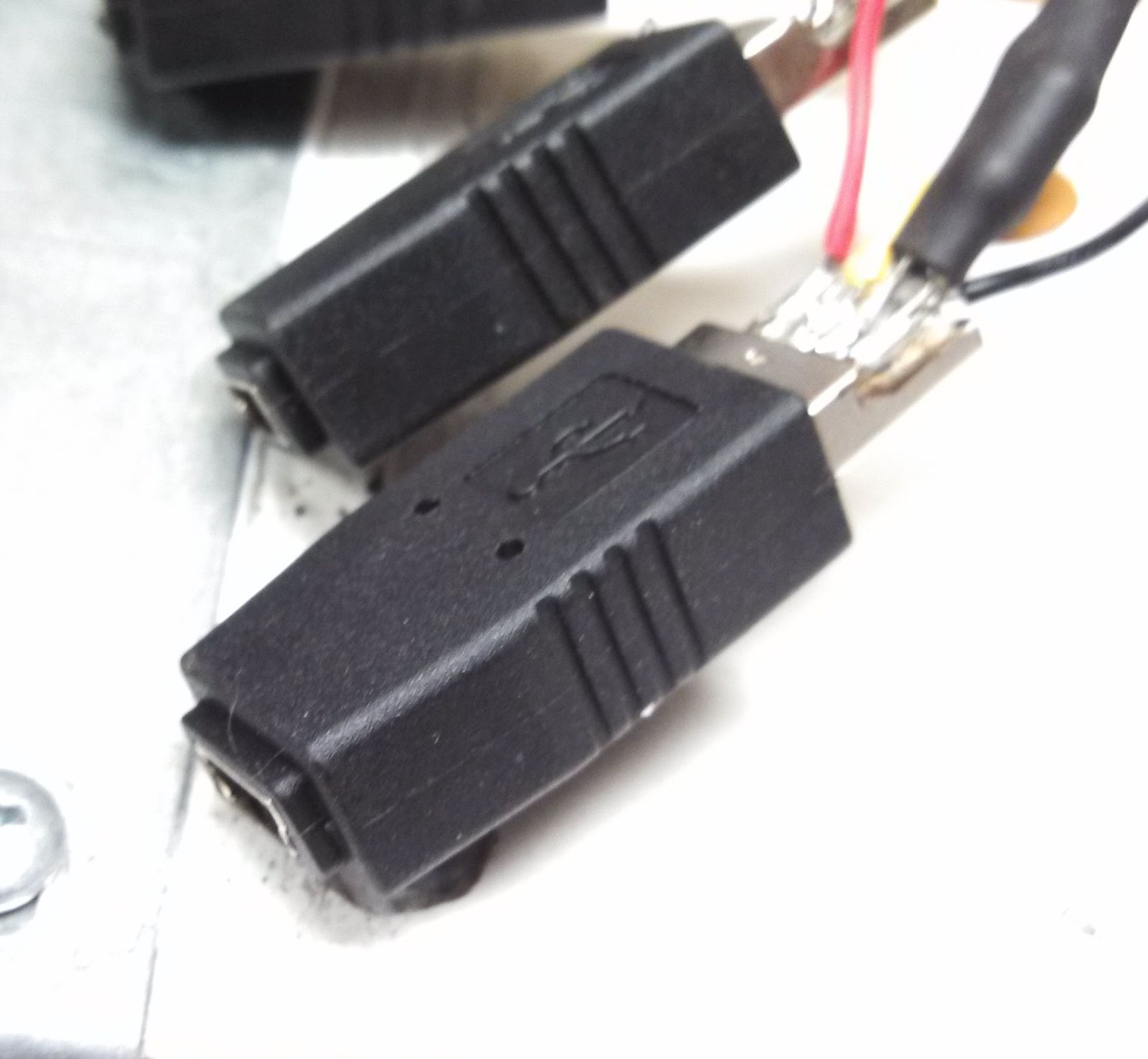 |
| Mini B USB adapters. |

Adapters wired to the Arduino.
I used a 3.5mm stereo headphone jack for the tachometer interface. If I get around to repackaging the Arduino I'll change it to another interface since the 3.5mm jack will short power to ground as the connector is inserted or removed, so you need to power down the Arduino before doing so. It's not a show stopper, but it is annoying. I've hot glued the connector so it can't accidentally pull out while in use. A 10K pull down resistor needed to be added to the tach sensor input.
I bought a small project box from Radio Shack, and aside from the very annoying issue with the Leonardo, the hardest part was installing everything inside the box. I machined slots in for the USB adapters to stick out through. I wedged them in there and glued them in place with epoxy. I also cut a hole for the USB cable which will provide power. To mount the Arduino I secured a thin piece of wood in the bottom of the project box, which the Arduino screwed to.
 |
| All packaged up. |
I then used Sugru to make the USB connectors look pretty, enclose the USB power cable, and provide it with strain relief. If you haven't used it before, Sugru is a really useful thing to have in your tool box. It comes in little packets and it's silicone rubber which sticks to most things and is moldable for 30 minutes after opening, and cures in 24-48 hours.
 |
| Sugru. |
 |
| The project box with Sugru added. |
After that the USB cable was hot glued into the USB jack on the Arduino, the unit was tested again, and then the top was screwed in place. Magnets were glued to the box and the box mounted on the back of the column. It draws its power form a Motorola cell phone charge.
 | |||||||
| All packed up and ready to go. |
There were issues with TouchDRO reading 20-40 times too low on the tachometer. After some time spent on the TouchDRO Google+ development forum I changed the Arduino sketch to one being developed by Ryszhard (http://www.rysium.com/rysium.docs/) and the tach immediately started working. I checked its readings against my laser tachometer and they match to within 20 RPM.
For my readout I'm using a 10" non-widescreen tablet, as I find the non-widescreen format works better for a DRO. This has been one of the best upgrades I could have possibly done and made the mill so much easier and nicer to use. I cannot recommend it enough, and I would never go back to not having one.
Mill: X Axis DRO Cover
Please read the complete article:
http://benchtopmachineshop.blogspot.com/2017/04/mill-touchdro.html
I'm using the iGaging linear scales for my DRO, and noticed my X axis would sometimes jump wildly before going back to normal. It turns out I'd gotten some tiny swarf inside the scale's body. After carefully cleaning it out, I used a 2" aluminum angle completely cover the scale. I needed to cut one side shorter so it would fit on top of the existing cover.
http://benchtopmachineshop.blogspot.com/2017/04/mill-touchdro.html
I'm using the iGaging linear scales for my DRO, and noticed my X axis would sometimes jump wildly before going back to normal. It turns out I'd gotten some tiny swarf inside the scale's body. After carefully cleaning it out, I used a 2" aluminum angle completely cover the scale. I needed to cut one side shorter so it would fit on top of the existing cover.
|
| DRO cover in place on X axis. |
Wednesday, August 9, 2017
Lathe: TouchDRO
I've wanted a DRO on my lathe for a while to deal with the back lash
and confusing dial markings. TouchDRO is the best way to go (for many reasons), but first I needed to attach digital scales to the carriage and cross slide.
The tachometer, like the mill's, uses a Hall effect sensor since they're much easier to set up than an optical sensor and are just as accurate in this application. The lathe previously had a spindle extension installed, and for the tach's magnet I drilled a hole on the extension and used JB Weld to mount a small neodymium magnet in it.
When
I do threading on the lathe I'll just back out my bit and run the lathe
in reverse to rest the carriage, so I have no need for a threading dial
and had removed it a while ago. That left a great threaded hole to
mount the scale bracket to. I suppose if you still have the threading
deal there you could always just sandwich the bracket between the apron
and dial. The bracket was easily made from 1/8" 1" aluminum angle. It's a
bit overkill and I'll probably trim it down a little more later, but
it's not really in the way as is.The screws holding the read head in
place use crazy glue as a thread locker, since Loctite will attack
plastics.
The design I ended up with places the scale below the lead screw, so it's fairly well protected from swarf. The mounting for it is quite stiff, so I only have the scale attached at one end. That was particularly helpful since I didn't want to try drilling into the lathe' body at the head since it houses the motor right there.The end of the scale was wrapped in electrical tape to electrically isolate the scale from the lathe.
The cross slide digital scale sits to the right of the cross slide. The
read head is screwed directly to the carriage and the scale's bracket is
connected slide itself. The bracket was made from a non-conducting
composite to electrically isolate the scale. The read head needed 1.5mm
machined off the cover's mating surface to lower below the height of the
cross slide. The read head is secured by two screws to insure it can't
rotate.
The design I ended up with places the scale below the lead screw, so it's fairly well protected from swarf. The mounting for it is quite stiff, so I only have the scale attached at one end. That was particularly helpful since I didn't want to try drilling into the lathe' body at the head since it houses the motor right there.The end of the scale was wrapped in electrical tape to electrically isolate the scale from the lathe.
 |
| Carriage scale in place with stock readout connected. Carriage travel at the extreme right of the bed is limited slightly. |
 |
| New iGaging scale mounted to cross slide |
 |
| Spindle extension with magnet mounted. |
The tach's sensor was mounted to the outside of the lathe's gear cover. I
considered mounting on the inside but space would have been an issue
and it works perfectly well on the outside. I covered the top of the
sensor with epoxy putty to protect it and keep any swarf from shorting
it. If you look closely you can see I've bent the sensor itself up and
away from the spindle to provide a better orientation to the magnet. The
sensor's USB cable is run down the back of the lathe to the Arduino's
case.
 |
| Hall effect sensor mounted on gear cover. |
Unlike the mill's Arduino, I constructed this one using a prototype
board. It's much cleaner and easier and I highly recommend it, even
though it added $8 to the build. I used standard USB A connectors for
the scales' interface since both connectors and cables are much easier
to find. This forced me to change the cables on both scales, but that
didn't cost much. The tachometer's plug is also USB to avoid the issue I
had using a 3.5mm headphone jack for the tach on the mill. Everything
was mounted in an old Dell laptop power supply brick's case I had on
hand. Neodymium magnets were glued to the case's top for mounting on the
back of the lathe.
I'm
using a Motorola RAZR phone as the Android device running the TouchDRO
application. Since the lathe only has four readouts (X,Z, diameter, and
tach) the phone is adequate. It's currently mounted with magnets to the
top of the headstock using a bracket I fabricated.
 |
| All done. |
Like with the mill, setting up a TouchDRO system has made the lathe a lot easier and nicer to use, and I would hate to ever be without it.
Subscribe to:
Posts (Atom)